Brake thread head device and forming method

A technology of brake device and brake line, which is applied in the field of brake line head device and forming, can solve the problems of uneven thickness, collapse, fracture, and missing, etc., and achieve the effect of not easy to collapse and fracture, and excellent practicability

Inactive Publication Date: 2014-08-20
ASHIMA LTD
View PDF6 Cites 2 Cited by
  • Summary
  • Abstract
  • Description
  • Claims
  • Application Information

AI Technical Summary

Problems solved by technology

[0005] The above two are related to the construction of the bicycle brake system. In the "Improved Structure of Bicycle Brake Handle", the brake line and the solid column, and the "brake handle structure that can be fixed to two sets of brake lines", the brake line and the stub. Nowadays, most of the molds are used to cover the solid column (short column) on one end of the brake line, but this method is prone to deviation due to external factors, for example: when the worker holds one end of the brake line When putting into the mold and preparing for casting, if the worker’s hand trembles slightly or the position of picking and placing is shifted, it will not be correctly aligned in the mold model, which will cause the solid column (short column) to be formed Finally, the thickness of each side cannot be equal. As a result, the brake line is easy to break and break from the thinner side of the solid column (short column) when the force is applied to drive the brake device, so that the brake line cannot drive the brake system. action, resulting in a dangerous absence for the rider

Method used


Image

  • Brake thread head device and forming method
  • Brake thread head device and forming method
  • Brake thread head device and forming method

Examples


Embodiment Construction

[0046] Regarding the technology, means and effects thereof adopted in the present invention, a preferred embodiment is given in detail in conjunction with the accompanying drawings. It is believed that the above-mentioned purpose, structure and characteristics of the present invention should be understood in depth and specifically .

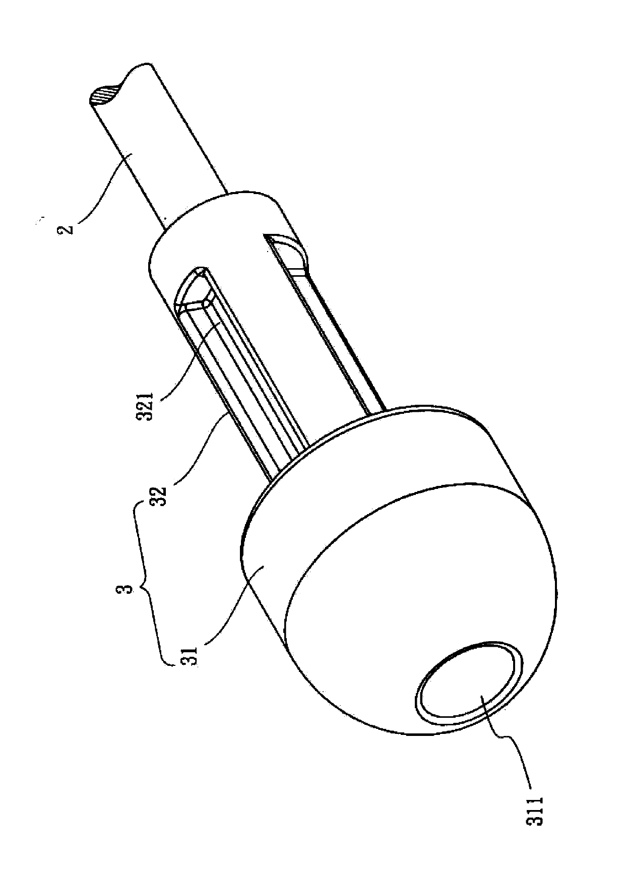
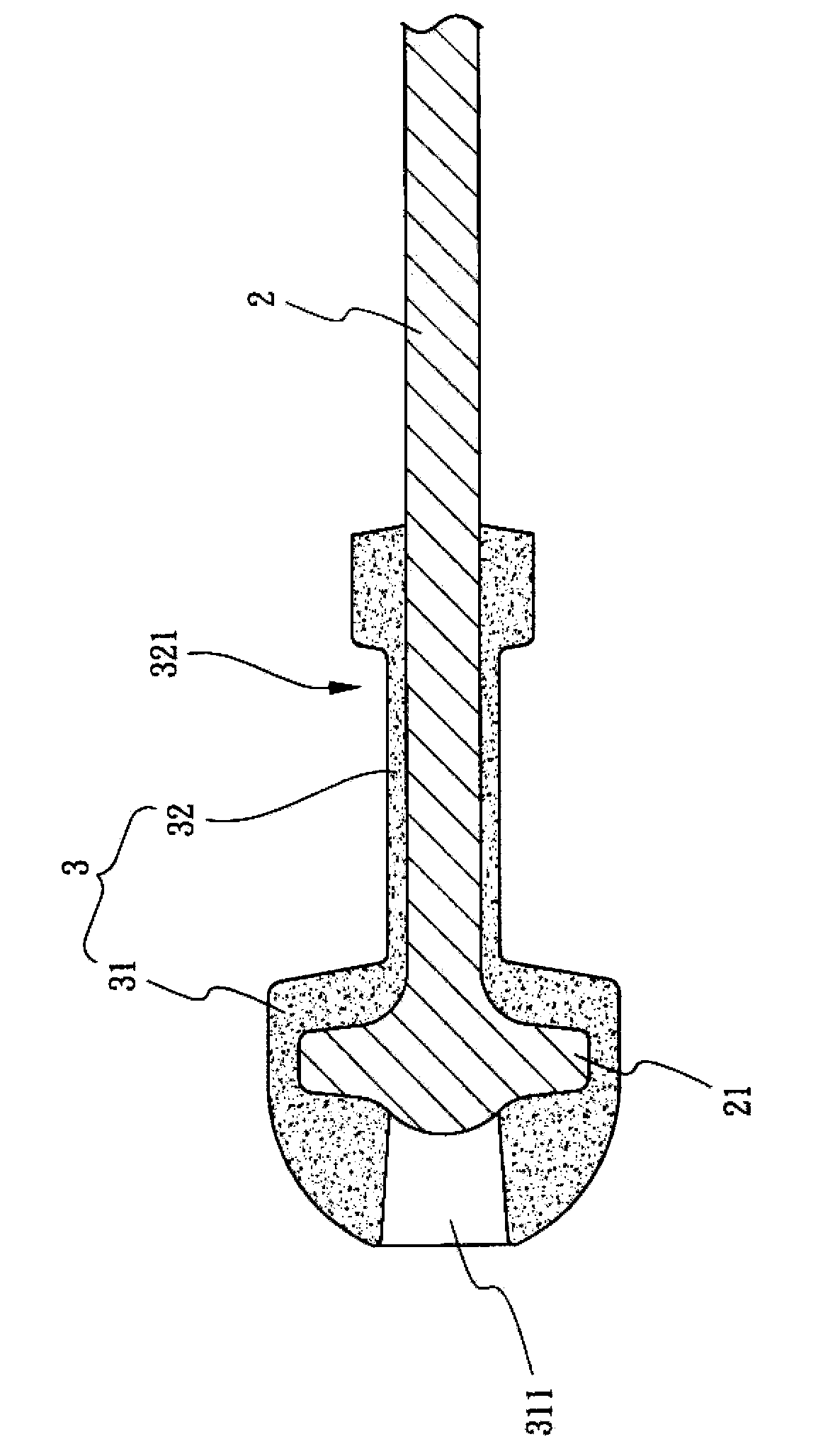
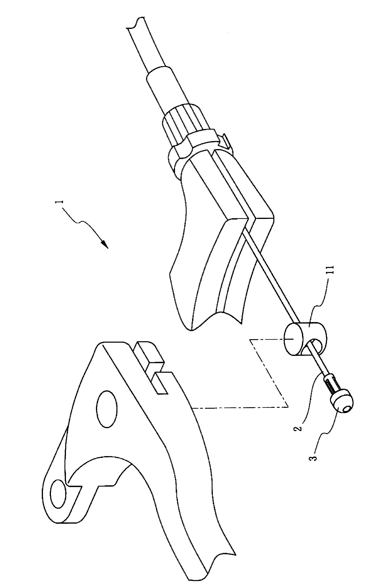
[0047] The following is an illustration of a preferred implementation mode, and does not limit the present invention in any form, see Figure 1 to Figure 3 As shown, wherein, the brake line end device of the present invention is assembled on the bicycle brake device 1, and is used to drive the brake device 1 to move, and it includes a core 2 and an ingot 3, wherein:

[0048] One end of the wire core 2 is provided with a knot 21, and the knot 21 is disc-shaped; the ingot 3 is wrapped around the end of the wire core 2 with the knot 21 and is conical, and the ingot 3 includes a A round head 31 and a body 32, the round head 31 is provided with a gro...


PUM


Abstract

A brake thread head device is arranged on a bicycle brake device in an assembled mode so as to drive the brake device to act. The brake thread head device comprises a thread core and a casting block. One end of the thread head is provided with a knot; the end, provided with the knot, of the thread core is coated with the casting block, the casting block comprises a circular head portion and a body portion, the circular head portion sinks downward from the top end towards the end, provided with the knot, of the thread core to form a slot channel, and the circumferential side of the body portion is provided with a plurality of slot holes which are arranged at intervals in a concave mode. A forming method of the brake thread head device includes the following steps of preparing and taking of material pieces, mold closing and limiting, positioning and rectifying, molding and forming and processing modification. Therefore, the thread core is coated with the casting block, one end of the thread core can be connected to the brake device in an assembled mode and stably fixed to the brake device in a clamped mode, and motion of the brake device can be controlled smoothly. According to the brake thread head device, when a user places the brake device into a mold, a brake thread can be accurately placed at an appropriate position of the mold, and thus finished molded products will not be uneven in thickness.

Description

technical field [0001] The present invention provides a brake wire end device and a forming method. Specifically, the operator can fix the position of each wire core when continuously placing it into the mold. Compared with the prior art, the processing efficiency is better, and It is not easy to have the characteristics of uneven coating of ingots, which is an invention with excellent practicability. Background technique [0002] Due to the fierce competition in the industry, in order to improve the competitive advantage, all walks of life are urged to continuously improve the technical field and precision standards of the industry, especially the bicycle industry is one of the most progressive industries. There are so many parts on the bicycle. Parts all occupy a very important position, and the brake system on the bicycle is related to the safety of the user, so it is more urgent for producers and users to pay attention to. [0003] In the brake system of a bicycle, ther...

Claims


Application Information

Patent Timeline
IPC IPC(8): B22D19/14
Inventor 莫韦恩
Owner ASHIMA LTD
Why Eureka
Try Eureka