
High-speed cylindrical roller bearing and integrated monitoring device thereof

A technology of cylindrical roller bearing and monitoring device, which is applied in bearing assembly, mechanical bearing testing, shaft and bearing, etc., can solve the problems of piezoelectric vibrator difficult to obtain kinetic energy, short overlapping time, and vibration, etc., and achieves novel structure and increased The effect of kinetic energy, power generation, and high reliability

Inactive Publication Date: 2014-08-13
ZHEJIANG NORMAL UNIVERSITY
View PDF7 Cites 15 Cited by
  • Summary
  • Abstract
  • Description
  • Claims
  • Application Information

AI Technical Summary

Problems solved by technology

[0004] The present invention provides a high-speed cylindrical roller bearing and its integrated monitoring device to solve the problems existing in the actual application of the existing bearing monitoring system and related piezoelectric power generation devices when the rotating speed is high, and the rotating magnet and the piezoelectric vibrator end The overlapping time between the external magnets is extremely short, and it is difficult for the piezoelectric vibrator to obtain enough kinetic energy to make it vibrate and generate electricity

Method used


Image

  • High-speed cylindrical roller bearing and integrated monitoring device thereof
  • High-speed cylindrical roller bearing and integrated monitoring device thereof
  • High-speed cylindrical roller bearing and integrated monitoring device thereof

Examples


Embodiment Construction

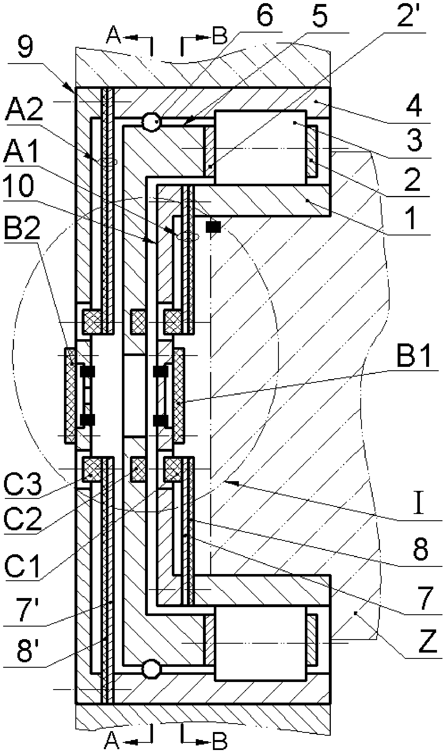
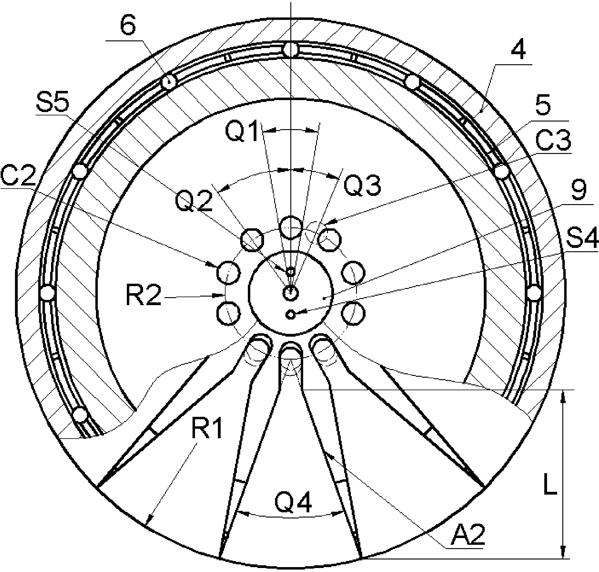
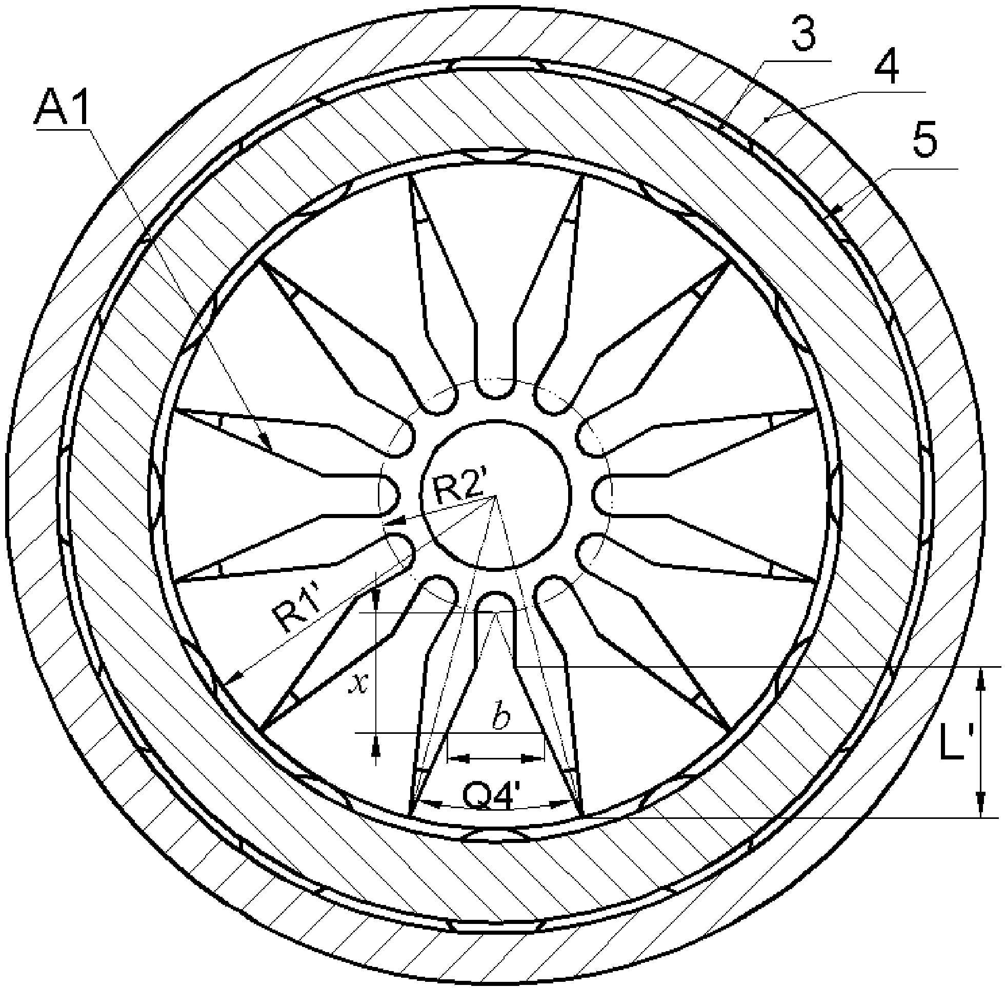
[0017] like Figure 1 to Figure 7 As shown, the present invention includes: an inner ring 1, a cage 21 and a cage two 2', a cylinder 3 for bearing bearing, an outer ring 4, an excitation disc 5, a ball 6 for positioning the excitation disc 5, and a fixed Disk 9, moving disk 10, cantilever beam piezoelectric vibrator 1 A1 and cantilever beam piezoelectric vibrator 2 A2, magnet 1 C1, magnet 2 C2 and magnet 3 C3, circuit board 1 B1 and circuit board 2 B2, temperature sensor S1, internal Ring vibration sensor S2, noise sensor S3, outer ring vibration sensor S4, speed sensor S5, and wires.

[0018] The inner ring 1 is narrower than the outer ring 4, and one side of the inner ring 1 and the outer ring 4 are aligned and installed, and the end face of the inner ring 1 on the non-aligned side is fixed with a moving disc 10 by screws, and the flange 101 of the end face of the moving disc 10 is aligned with the inner ring 1. A cantilever beam-type piezoelectric vibrator-A1 bonded by a m...


PUM


Abstract

The invention relates to a high-speed cylindrical roller bearing and an integrated monitoring device of the high-speed cylindrical roller bearing and belongs to the technical field of bearings and monitoring technologies of the bearings. A movable disc and a fixed disc are installed on an inner ring and an outer ring of the bearing respectively. A cantilever beam type piezoelectric vibrator is connected between the inner ring and the movable disc in a pressing mode, and a cantilever beam type piezoelectric vibrator is connected between the outer ring and the fixed disc in a pressing mode. Excited magnets are installed at the free ends of the piezoelectric vibrators. The movable disc and the fixed disc are respectively provided with a circuit board and different types of sensors. An excitation disc and holders are installed in a riveted mode. Limiting balls are arranged between the excitation disc and the inner surface of the outer ring. An excitation magnet is installed on the excitation disc. The integrated monitoring device has the advantages that the monitoring device and the bearing are integrated, and the integrated monitoring device has a self-energy-supplying sensing monitoring function and can be used as an independent component without changing the equipment structure; the piezoelectric vibrators are excited based on a differential motion principle, and kinetic energy and generating capacity obtained by the piezoelectric vibrators can be effectively increased at the time of high speed; the structure size of the piezoelectric vibrators and the arrangement of the excitation magnet are reasonable, piezoelectric plates only bear pressure stress without twisting, and reliability is high.

Description

technical field [0001] The invention belongs to the technical field of rolling bearings and monitoring thereof, and in particular relates to a high-speed cylindrical roller bearing and an integrated monitoring device thereof. Background technique [0002] Bearing is a typical mechanical basic part, which is widely used in the fields of machinery, vehicles, aerospace, ships and energy; however, bearing is also one of the most vulnerable parts in rotating machines, and 30% of rotating machinery failures % is caused by bearing failure. Therefore, the state monitoring and early fault diagnosis of bearings have attracted people's attention. On-line monitoring of bearing status has gradually become an indispensable technology in the fields of large generators, ships, high-speed rail, and aircraft. The indicators to be monitored include temperature, vibration, speed, and noise. Early bearing monitoring systems were mainly plug-in. One of the disadvantages was that the distance be...

Claims


Application Information

Patent Timeline
IPC IPC(8): H02N2/18F16C41/00G01M13/04
Inventor 阚君武张肖逸王淑云曾平刘殿龙
Owner ZHEJIANG NORMAL UNIVERSITY
Learn More