


Quick Research
Generate reliable direction feasibility study reports for your R&D in just a few steps.

Technical Q&A
Discover and master advanced knowledge NOW. Basics, ideas, possibilities, all at once.

Find Solutions
As an expert in R&D theories, this can generate solutions to your technical problems instantly.

Evaluate Feasibility
Analyze your overall solution with one click, know your potential R&D risks in advance.

Monitor Landscape
Get weekly tech updates, stay abreast of the latest tech innovations and key insights.
A method for locating the touch area of a touch screen
A technology of touch area and positioning method, which is applied in the direction of instruments, calculations, electrical digital data processing, etc., can solve the problems of time-consuming, etc., and achieve the effects of saving time, improving recognition efficiency, and narrowing the judgment range
- Summary
- Abstract
- Description
- Claims
- Application Information
AI Technical Summary
Problems solved by technology
Method used
Image

Examples
Embodiment 1
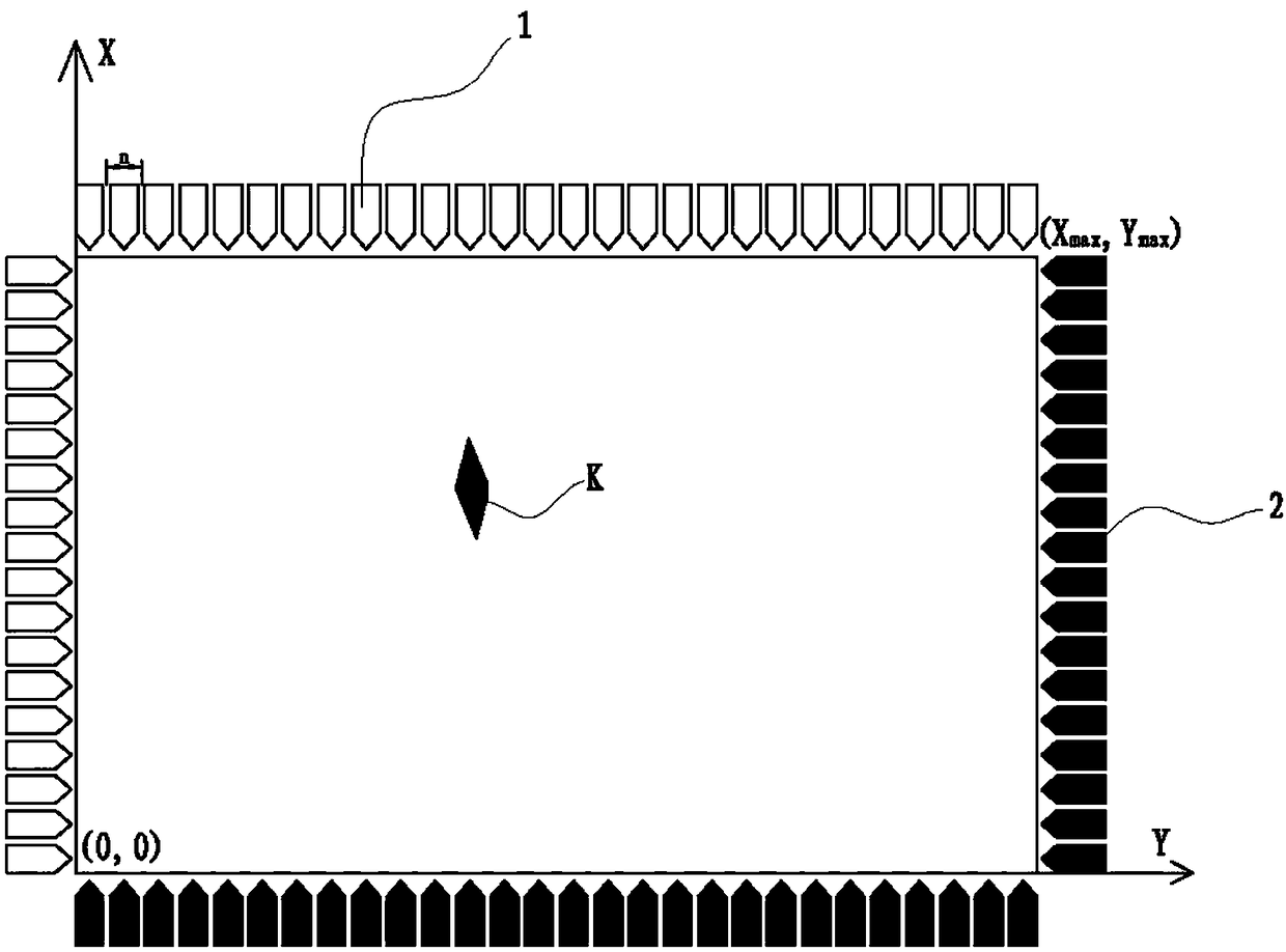
[0024] Embodiment 1: as figure 1 As shown, the four sides of the touch screen are respectively provided with an infrared emitting element 1 and an infrared receiving element 2 .
[0025] Assume that an optical path from one infrared emitting element 1 to one infrared receiving element 2 is a unit optical path.
[0026] Taking the infrared emitting element 1 as the starting point of the optical path, and the infrared receiving element 2 as the end point of the optical path, the optical width of the starting point of the optical path determined by each infrared emitting element 1 should be equal to the optical width of the end point of the optical path determined by each infrared receiving element 2, assuming The light width of the starting point of the light path determined by each infrared emitting element 1 is the unit light width.
[0027] According to the resolution of the touch screen, determine the unit light width as n; thus establish a coordinate XY system, such as fi...
Embodiment 2
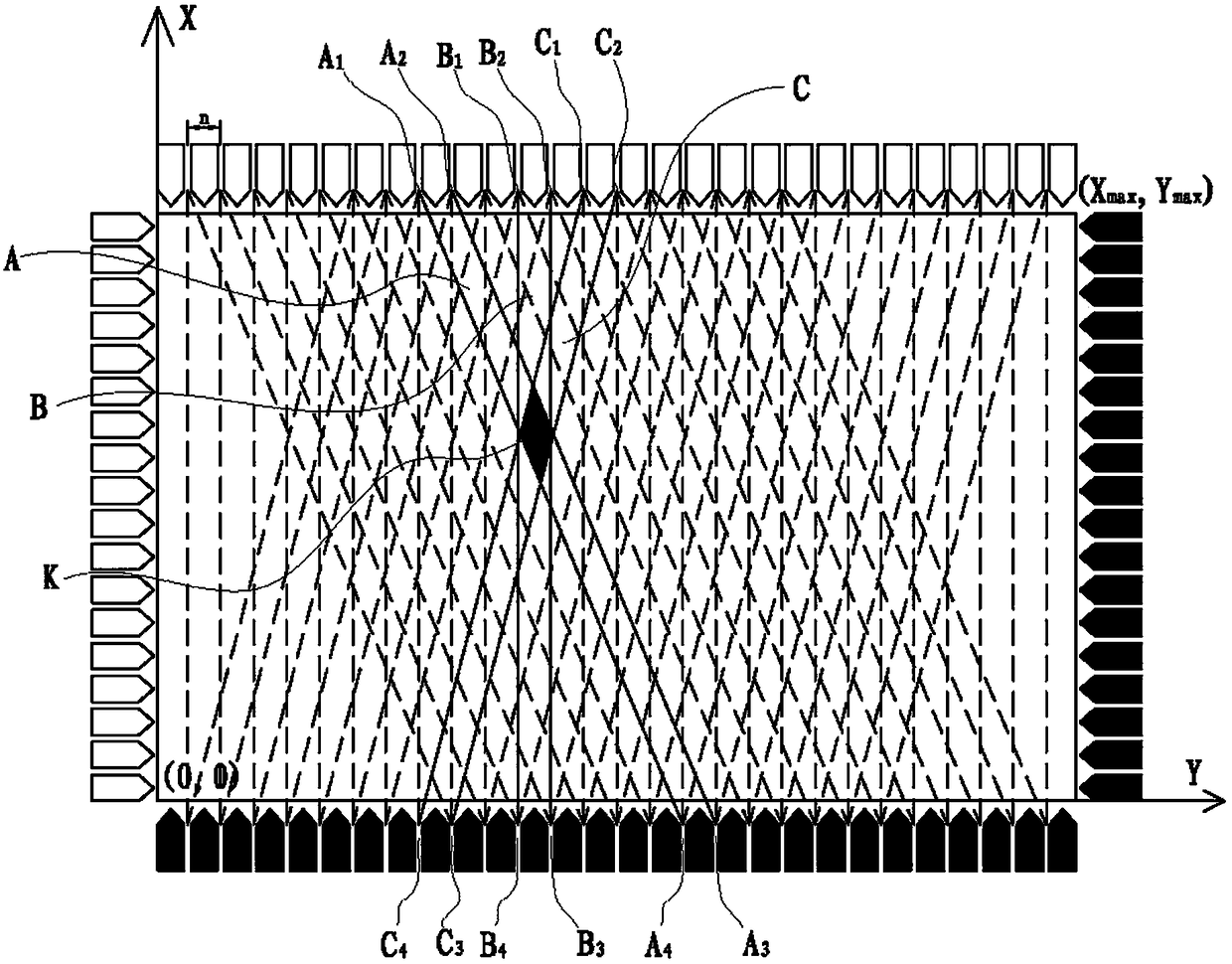
[0061] Embodiment 2: as figure 1 As shown, the area K where the touch area occurs, the identification steps of the area K are as follows,
[0062] (1) In one frame, scan all optical path layers, and figure 2 In , the dotted line and the solid line at the same angle represent a layer of optical path, and all blocked unit optical paths are obtained. There are three unit optical paths, namely A, B, and C, such as figure 2 The solid line area in the middle, and obtain the coordinates of the three light paths, that is, the four vertices of the light path A are A 1 (X a1 , Y a1 ), A 2 (X a2 , Y a2 ), A 3 (X a3 , Y a3 ), A 4 (X a4 , Y a4 ), since the three light paths are unit light paths, X a2 -X a1 = n, Y a1 =Y a2 =Y max , X a3 -X a4 = n, Y a3 =Y a4 =0;
[0063] The four vertices of light path B are B 1 (X b1 , Y b1 ), B 2 (X b2 , Y b2 ), B 3 (X b3 , Y b3 ), B 4 (X b4 , Y b4 ), since the three light paths are unit light paths, X b2 -X b1 = n, Y...
Embodiment 3
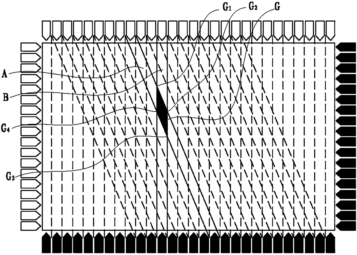
[0068] Embodiment 3: Generate at least two touch points at the same time. The recognition method is similar to Embodiment 1, except that when calculating the polygon result coordinates, two or more polygon result coordinates are calculated at the same time.
PUM
 Abstract
Description
Claims
Application Information
 - R&D Engineer
- R&D Manager
- IP Professional
- Industry Leading Data Capabilities
- Powerful AI technology
- Patent DNA Extraction
Browse by: Latest US Patents, China's latest patents, Technical Efficacy Thesaurus, Application Domain, Technology Topic, Popular Technical Reports.
© 2024 PatSnap. All rights reserved.Legal|Privacy policy|Modern Slavery Act Transparency Statement|Sitemap|About US| Contact US: help@patsnap.com