Automatic speed change gear with torsion limiting clutch and speed change shaft
A technology of automatic transmission and clutch, applied in the direction of clutch, transmission, automatic clutch, etc., can solve the problems of high manufacturing cost, complex structure, and inability to realize reverse output.
- Summary
- Abstract
- Description
- Claims
- Application Information
AI Technical Summary
Problems solved by technology
Method used
Image
Examples
Embodiment 1
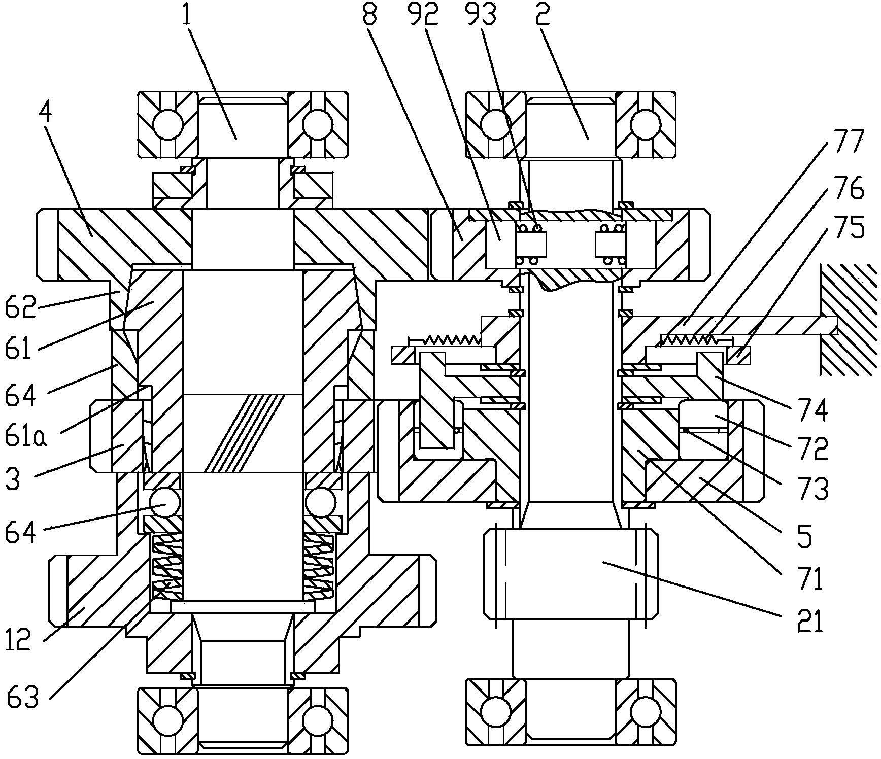
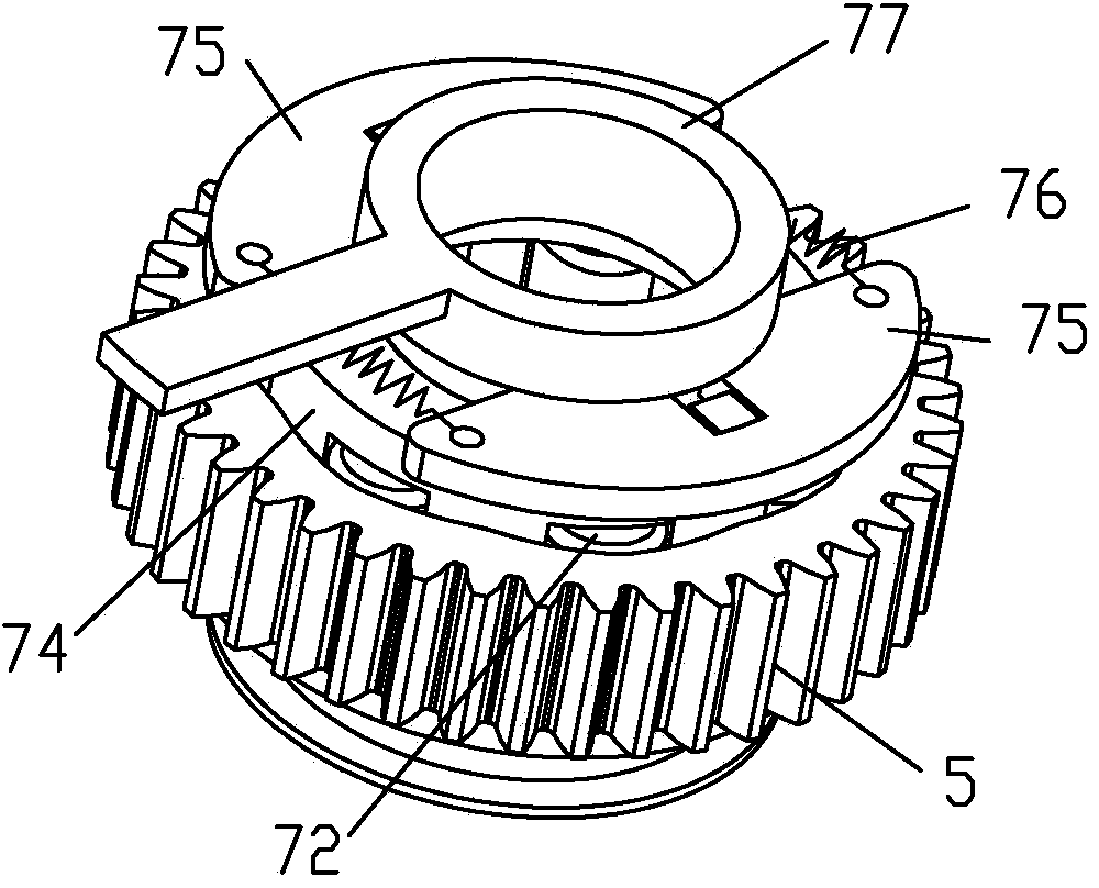
[0042] Example 1 see figure 1 , figure 2 , image 3 , Figure 4, Figure 5 , an automatic transmission device containing a torque-limiting clutch, comprising a driving shaft 1 and a driven shaft 2, the driving shaft 1 and the driven shaft 2 are respectively provided with a pair of high-speed gears and a pair of low-speed gears corresponding to constant meshing, said The high-speed driving gear 4 of the high-speed gear pair is rotatably connected to the drive shaft 1, and a normally closed conical disc friction torque-limiting clutch is arranged between the high-speed gear driving gear 4 and the drive shaft 1. The loading spring 63 is connected between a journal end face of the driving shaft 1 and an end face of the driving cone 61 of the friction torque limiting clutch, and an end face bearing 64 is arranged between the driving cone 61 and the loading spring 63; the driving cone 61 There is also a torque transmission structure for power transmission between the drive shaf...
Embodiment 2
[0053] Embodiment 2 see Image 6 , Figure 7 , the low gear drive gear 3 is integrated with the drive cone 61; the end face bearing 64 is connected between the loading spring 63 and the low gear drive gear 3; the drive cone 61 is connected to the drive shaft 1 There is a torque transmission structure for power transmission, which is an end face cam pair structure, including the cam pair driving part 11 fixedly connected to the driving shaft 1, integrally formed on the driving cone 61 of the friction torque limiting clutch The cam pair passive part 41, the cam pair active part 11 and the cam pair passive part 41 are provided with V-shaped groove cam surfaces on the opposite end faces, and the protruding parts of the end faces of the active part 11 and the passive part 41 of the cam pair correspond to the V The depressions of the V-shaped grooves are complementary, and the slopes on both sides of the V-shaped grooves are symmetrical. The torque transmission structure is used t...
Embodiment 3
[0056] Embodiment 3 see Figure 8 , the low gear driving gear 3 is coaxially fixedly connected to the driving shaft 1; the power input gear 12 is fixedly connected to the driving cone 61 of the friction torque limiting clutch; the driving cone 61 is connected to the driving shaft 1 The torque transmission structure of the helical spline fit structure is also provided between the power input gear 12 and the drive shaft 1; the loading spring 63 is connected between the drive cone 61 and the shoulder of the drive shaft 1.
[0057] The rest of the structure of this embodiment is the same as that of Embodiment 1, and will not be repeated here.
PUM
 Abstract
Description
Claims
Application Information
 - R&D
- Intellectual Property
- Life Sciences
- Materials
- Tech Scout
- Unparalleled Data Quality
- Higher Quality Content
- 60% Fewer Hallucinations
Browse by: Latest US Patents, China's latest patents, Technical Efficacy Thesaurus, Application Domain, Technology Topic, Popular Technical Reports.
© 2025 PatSnap. All rights reserved.Legal|Privacy policy|Modern Slavery Act Transparency Statement|Sitemap|About US| Contact US: help@patsnap.com


