
Feedforward Dynamic Spool Valve

A sliding valve, actuation technology, applied to non-mechanically actuated valves, valve devices, engine components, etc., can solve problems such as engine parts degradation and engine knocking

Active Publication Date: 2018-02-09
FORD GLOBAL TECH LLC
View PDF6 Cites 0 Cited by
  • Summary
  • Abstract
  • Description
  • Claims
  • Application Information

AI Technical Summary

Problems solved by technology

This can lead to unwanted engine knock and subsequent degradation of engine parts

Method used


Image

  • Feedforward Dynamic Spool Valve
  • Feedforward Dynamic Spool Valve
  • Feedforward Dynamic Spool Valve

Examples


Embodiment Construction

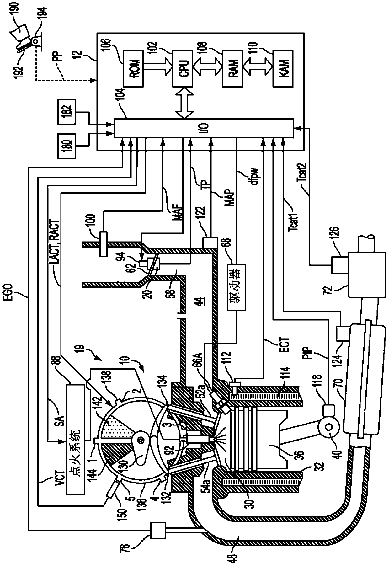
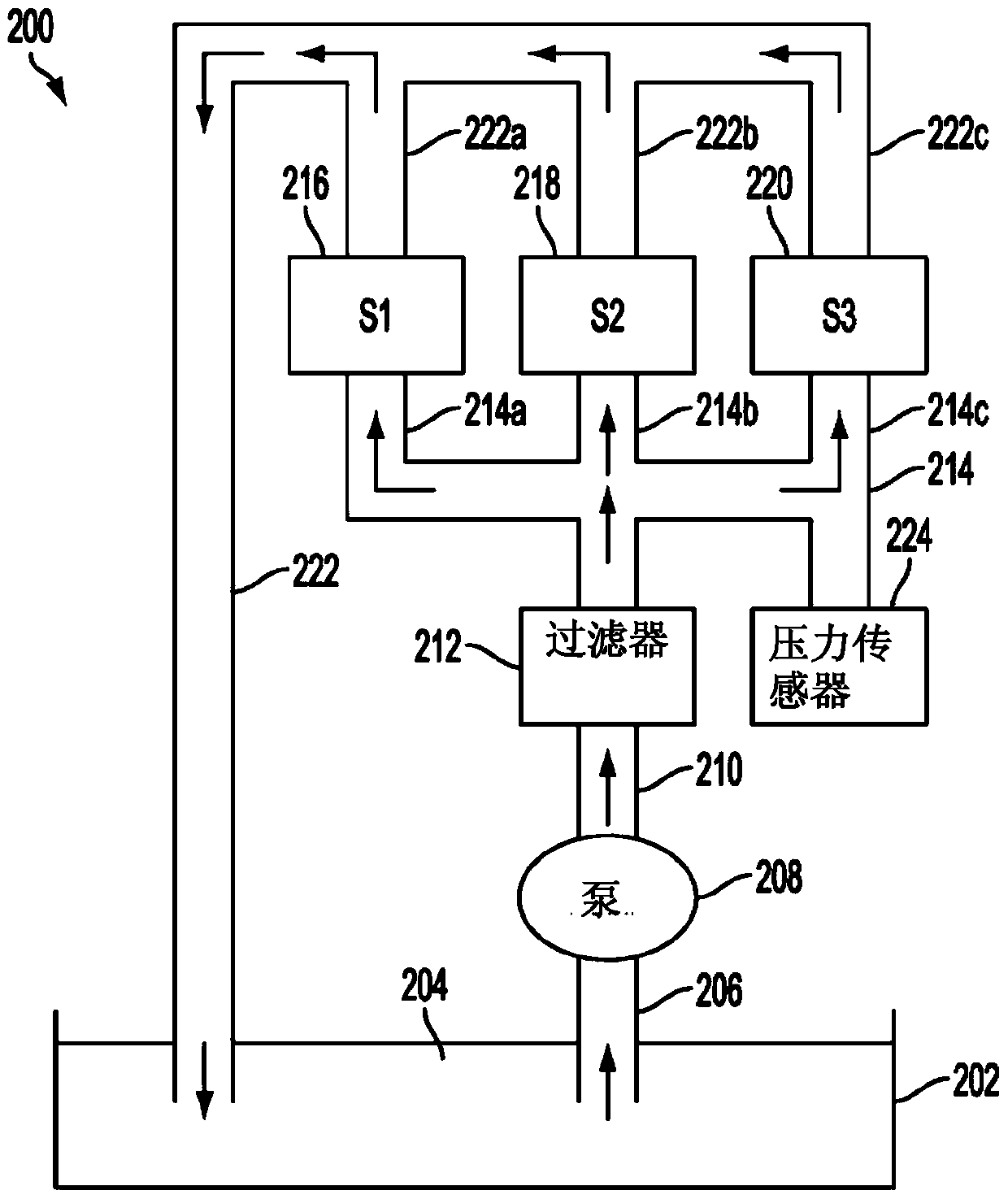
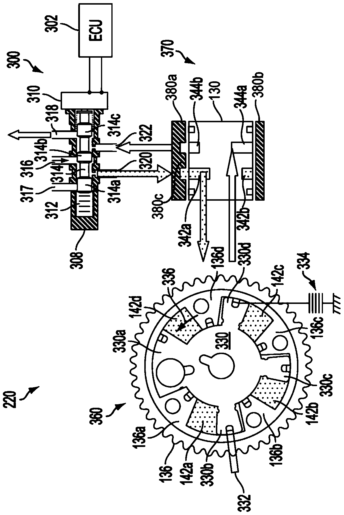
[0018] The following description relates to systems and methods for controlling a vehicle engine having a variable cylinder valve system such as variable cam timing. For example, the engine may include VCT phasers used to adjust cam timing, where the phasers are included in the hydraulic system. The engine may be configured to include a controller configured to control the actuation signal of the solenoid, thereby controlling the position of the spool valve placed within the hydraulic system. In one example, the solenoid actuation signal may be subjected to feed-forward modulation to maintain the spool valve position, thereby blocking oil from being drained from the hydraulic system, thereby improving the performance of the VCT system.

[0019] figure 1 An exemplary embodiment of a combustion chamber or cylinder of internal combustion engine 10 is described. figure 1 Engine 10 is shown as capable of receiving control parameters from a control system including controller 12 ,...


PUM


Abstract

The present invention describes a method of controlling a spool valve through a feedback and feedforward mechanism. In one example, the method includes actuating a spool valve via a solenoid to advance and retard a hydraulic variable cam timing actuator coupled to a camshaft and commanded to zero to maintain the current cam timing by means of A component whose frequency is synchronized with the engine firing frequency modulates the solenoid to counteract cam torque oscillations. In this way, the spool can be maintained at zero despite high cam torque oscillation frequency, thereby preserving oil in the solenoid assembly and improving cam timing.

Description

technical field [0001] The invention relates to a feedforward dynamic slide valve. Background technique [0002] Internal combustion engines may use variable cam timing (VCT) to improve a vehicle's fuel economy and emissions performance. One of these methods is variable cam timing using an oil-actuated device such as a vane cam phaser. The phaser can be controlled by an electromechanically actuated spool valve that directs oil flow to one side of the vane or the other. The performance of the device is thus dependent on the oil pressure, which may be a function of engine speed and leakage through various oil systems. [0003] An exemplary VCT system uses a spool valve with one inlet flow and two outlet flows. The spool valve thus has two functions - controlling the entry of oil and the exit of oil. Feedback and / or feedforward methods are often used to control VCT position when controlling oil inlet. [0004] The inventors herein have recognized that when cam timing is ma...

Claims


Application Information

Patent Timeline
Patent Type & Authority Patents(China)
IPC IPC(8): F02D13/00F01L1/344F01L9/02
CPCF01L2001/3443F01L1/3442C07B2200/13C07D409/04
Inventor J·W·丘奇
Owner FORD GLOBAL TECH LLC
Learn More