
Main reducer for coaxial dual-rotor high-speed helicopter with tension paddle

A technology of coaxial dual rotors and final reducer, which is applied to rotorcraft, aircraft, motor vehicles, etc., can solve the problems of long take-off runway and taxiing distance, limit the flight speed of helicopters, limit the flight height of helicopters, etc., and achieve the reduction of additional Effect of loss and resistance, high load, low vibration and noise

Active Publication Date: 2014-08-13
黄山市开发投资集团有限公司
View PDF6 Cites 21 Cited by
  • Summary
  • Abstract
  • Description
  • Claims
  • Application Information

AI Technical Summary

Problems solved by technology

[0004] 1. The main reducer composed of multi-stage gear transmission is characterized by a simple structure, but the load capacity and efficiency are low, the range of transmission ratio is small, and the number of rotors that can be used to provide power is small, which limits the flying speed of the helicopter;
[0005] 2. The power output rotor only has the main reducer with the front pull propeller. Although the speed can meet the requirements, due to the lack of lift provided by the vertical rotor, the helicopter equipped with the main reducer of this transmission system is limited in flying height. Longer take-off runways and taxiing distances are required during the take-off phase, and the take-off time is also longer;
[0006] 3. The dual-rotor with coaxial inversion is adopted. Although there are two rotors on the power output, it can take off on a short runway, and there is no need to configure the tail structure. The overall performance can meet the requirements of high-speed helicopters in terms of power, but The speed is limited by the arrangement of the rotor, and there is still room for improvement

Method used


Image

  • Main reducer for coaxial dual-rotor high-speed helicopter with tension paddle
  • Main reducer for coaxial dual-rotor high-speed helicopter with tension paddle
  • Main reducer for coaxial dual-rotor high-speed helicopter with tension paddle

Examples


Embodiment Construction

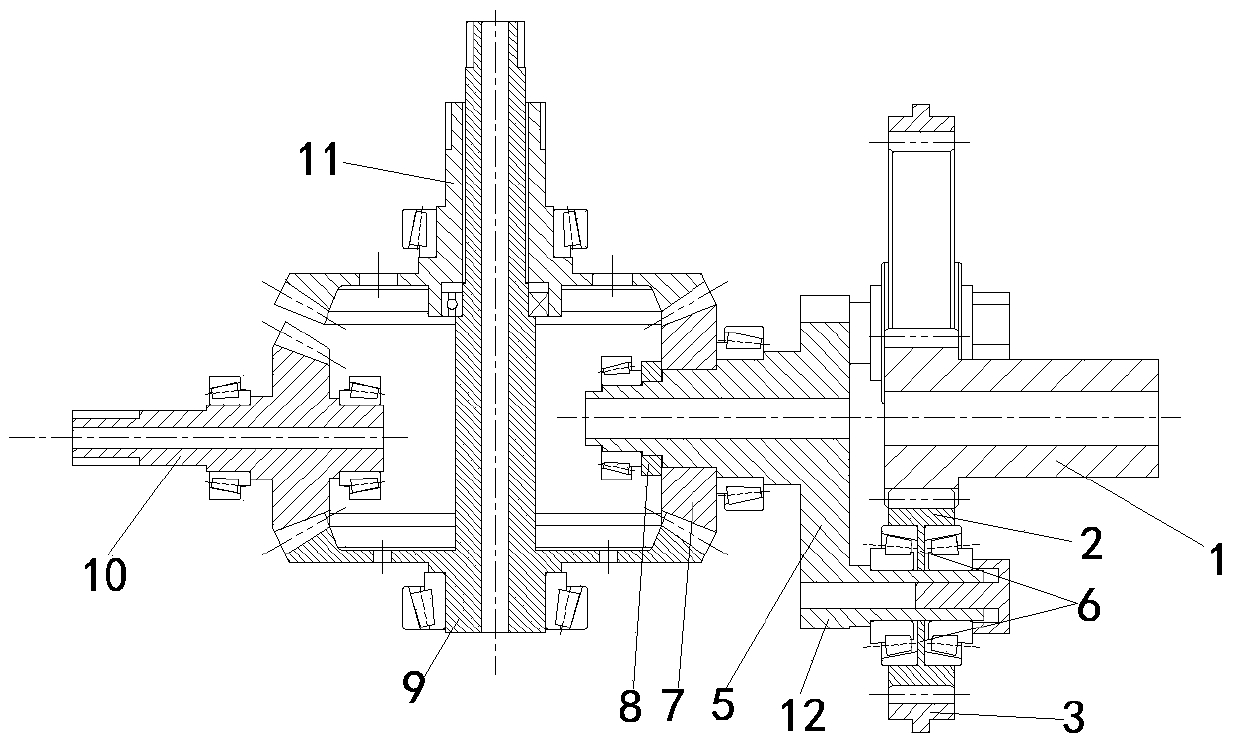
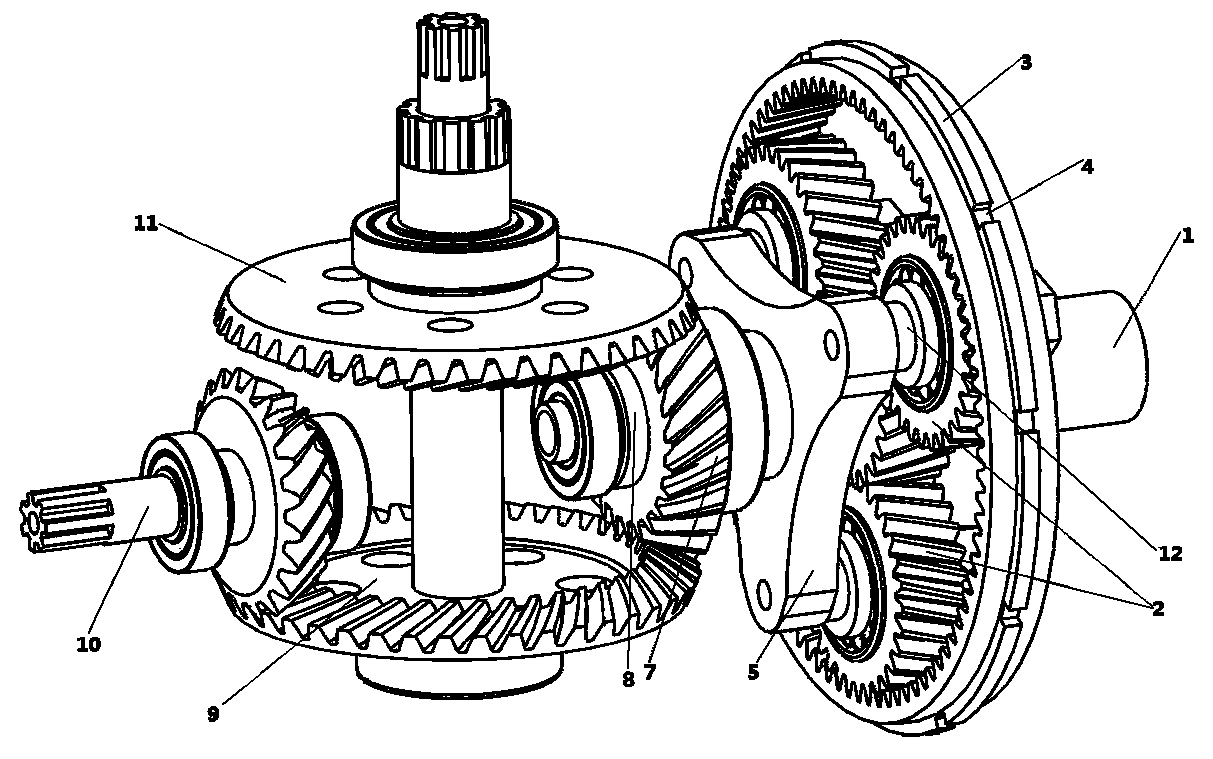
[0032] see figure 1 , figure 2 . A main reducer for a coaxial dual-rotor high-speed helicopter with a pull paddle, including a 2K-H helical planetary gear train composed of a sun gear input shaft 1, a fixed ring gear 3, three planetary gears 2 and a planet carrier 5, It also includes an input gear 7, an upper rotor gear shaft 11, a lower rotor gear shaft 9 and a pull paddle output gear shaft 10; the sun gear input shaft 1 is an involute helical gear shaft.

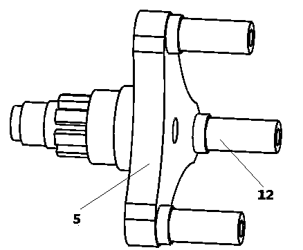
[0033] see image 3 . The main shaft at one end of the planetary carrier 5 is a shoulder shaft, the waist of the main shaft is provided with splines, and the other end of the planetary carrier 5 is provided with three planetary wheel shafts 12 .

[0034] see Figure 4 . The inner ring teeth of the fixed ring gear 3 are involute helical teeth, and the outer ring is provided with a shaft shoulder, and several key grooves 4 are evenly distributed on the shaft shoulder of the fixed ring gear 3 in the circumferential ...


PUM


Abstract

The invention relates to a main reducer for a coaxial dual-rotor high-speed helicopter with a tension paddle. The main reducer comprises a 2K-H helical tooth planetary gear train (consisting of a sun wheel input shaft, planet wheels and a planet carrier) and a spiral bevel gear differential gear train (consisting of an input gear, an upper rotor gear shaft, a lower rotor gear shaft and a tension paddle output gear shaft). The sun wheel input shaft transmits input torque through the 2K-H helical tooth planetary gear train and drives the input gear to perform transmission to realize coaxial reversal output torque of the upper rotor gear shaft and the lower rotor gear shaft in the spiral bevel gear differential gear train and output torque of the tension paddle output gear shaft. Such characteristics of the spiral bevel gear as high transmission efficiency, low vibration noise and high bearing capacity are combined with such advantages of the planetary gear train as compact structure and large transmission ratio. The front tension paddle is combined with coaxial dual rotor wings through power output, the requirements of the high-speed helicopter on high-speed flight and powerful power improvement can be met, and the invention has a certain guiding significance for design of the main reducer of the helicopter.

Description

technical field [0001] The invention relates to a transmission system of a high-speed helicopter, in particular to a main reducer for a coaxial double-rotor high-speed helicopter with a pull paddle. Background technique [0002] Helicopter transmission system, rotor system and engine are called the three key moving parts of helicopter. The role of the helicopter transmission system is to transmit the output power and output speed of the engine to the rotor, tail rotor and various accessories in a certain proportion. It is an indispensable transmission component and the only transmission path for the power output of the turboshaft engine. Its transmission features are: high speed, heavy load, large transmission ratio, high reliability, low vibration and noise and good maintainability. [0003] At present, the main structure of the main reducer of high-speed helicopters is as follows: [0004] 1. The main reducer composed of multi-stage gear transmission is characterized by ...

Claims


Application Information

Patent Timeline
IPC IPC(8): B64C27/605B64C27/08
Inventor 周志红黄康赵韩刘鹏
Owner 黄山市开发投资集团有限公司
Learn More