clipper

A technology of flying shears and shearing arms, which is applied in the field of flying shears, can solve the problems that the flying shears cannot normally cut the rolled piece, the rolled piece is deformed, and the accident of stacking steel, so as to prevent stacking of steel, reduce production loss, and improve The effect of yield

Active Publication Date: 2016-05-04
NANJING JINXIN TRANSMISSION EQUIP
View PDF6 Cites 0 Cited by
  • Summary
  • Abstract
  • Description
  • Claims
  • Application Information

AI Technical Summary

Problems solved by technology

When the flying shear is cut, the rolled piece moves to the cutting place of the flying shear through the guide groove. At this time, because the rolling speed of the wire rod is relatively fast, if the head and tail of the rolled piece are not smooth, or the rolled piece is deformed, the general wire The shear arm structure of the flying shear will cause the flying shear to not cut the rolled piece normally, which will easily lead to the occurrence of steel stacking accidents

Method used


Image

  • clipper
  • clipper
  • clipper

Examples


Embodiment Construction

[0015] The present invention will be further described below in conjunction with the accompanying drawings and specific embodiments.

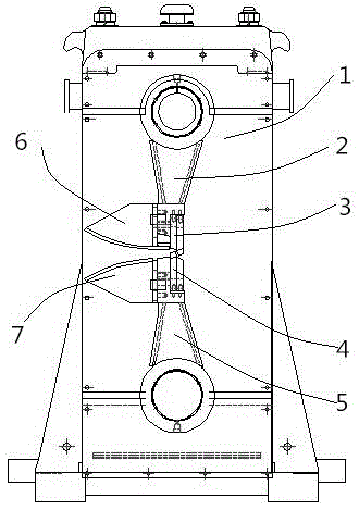
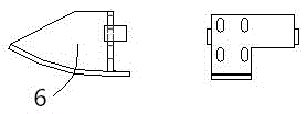
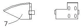
[0016] Such as figure 1 Shown, a kind of flying shears comprises flying shears body 1, upper shear arm 2, pressing plate 3, cutting edge 4, lower shear arm 5, upper guide plate 6 and lower guide plate 7, is provided with on flying shears body 1 On the upper shear arm 2 and the lower shear arm 5, an upper guide plate 6 is provided on the feed side of the upper shear arm 2, and a lower guide plate 7 is provided on the feed side of the lower shear arm 5, and on the upper shear arm 2 and the lower shear arm 5 Each is provided with a cutting edge 4 for cutting, and the cutting edge 4 is respectively fixed by a pressing block 3; on the upper shear arm 2, the pressing block 3 for fixing is arranged between the upper guide plate 6 and the cutting edge 4; On the arm 5 , the cutting edge 4 is arranged between the lower guide plate 7 and the pressing bl...


PUM


Abstract

The invention discloses a flying shear, which belongs to the technical field of metallurgical steel rolling equipment. An upper guide plate is provided on the side, and a lower guide plate is provided on the feeding side of the lower shear arm. Both the upper guide plate and the lower guide plate are arc-shaped structures; For the cutting blade, the cutting blades are respectively fixed by pressing blocks; on the upper shearing arm, the pressing block used for fixing is set between the upper guide plate and the cutting edge; on the lower shearing arm, the cutting edge is set between the lower guide plate and the pressing block Between; After matching, a gradually shrinking feed inlet is formed between the upper guide plate and the lower guide plate until it meets the cutting edge. The flying shear of the present invention can prevent the phenomenon of stacking steel when the rolled piece is sheared, and at the same time, the broken ends of the rolled piece can be smoothly dropped into the waste collection device, without affecting the normal shearing of the next flying shear. cut.

Description

technical field [0001] The invention belongs to the technical field of metallurgical steel rolling equipment, and in particular relates to a flying shear. Background technique [0002] On the steel rolling equipment line in the metallurgical industry, the rolling mill continuously rolls the billet to form the billet. However, during the rolling process, due to cracking, unevenness, or deformation of the head and tail of the rolled piece, steel stacking accidents are prone to occur; This requires cutting the head and tail of the rolled piece. When the flying shear is cut, the rolled piece moves to the cutting place of the flying shear through the guide groove. At this time, because the rolling speed of the wire rod is relatively fast, if the head and tail of the rolled piece are not smooth, or the rolled piece is deformed, the general wire The shear arm structure of the flying shear will cause the flying shear to fail to cut the rolled piece normally, which will easily lead ...

Claims


Application Information

Patent Timeline
Patent Type & Authority Patents(China)
IPC IPC(8): B23D25/02B23D33/02
Inventor 戴益民章宇顺聂启春
Owner NANJING JINXIN TRANSMISSION EQUIP
Why Eureka
Try Eureka