Installing structure and process for vacuum switch tube

A technology of vacuum switch tube and installation structure, which is applied to electric switches, high-voltage/high-current switches, high-voltage air circuit breakers, etc., can solve the problems of installation difficulty, damage to bellows, affecting the sealing performance of insulating cylinders, etc., and achieve a simple installation structure. , reliable connection, cleverly designed effects

Active Publication Date: 2014-08-06
SHANGHAI GDE ELECTRIC
View PDF6 Cites 4 Cited by
  • Summary
  • Abstract
  • Description
  • Claims
  • Application Information

AI Technical Summary

Problems solved by technology

When installing a vacuum switch tube in a solid insulated ring network cabinet, if the driven contact end exerts force to rotate, it may cause damage to the bellows, and the only way to complete the installation is to apply force to rotate from the static contact end
At present, there are also manufacturers who screw in the screws from the outside of the insulating cylinder to complete the installation of the vacuum switch tube, but this solution will affect the tightness inside the insulating cylinder
[0003] In addition, the inner space of the insulating cylinder of the solid insulated ring network cabinet is small, and the static contact of the vacuum switch tube needs to be reliably connected to the conductor embedded in the bottom of the insulating cylinder, which brings considerable difficulties for the installation of the vacuum switch tube inside the insulating cylinder difficulty

Method used


Image

  • Installing structure and process for vacuum switch tube
  • Installing structure and process for vacuum switch tube
  • Installing structure and process for vacuum switch tube

Examples


Embodiment Construction

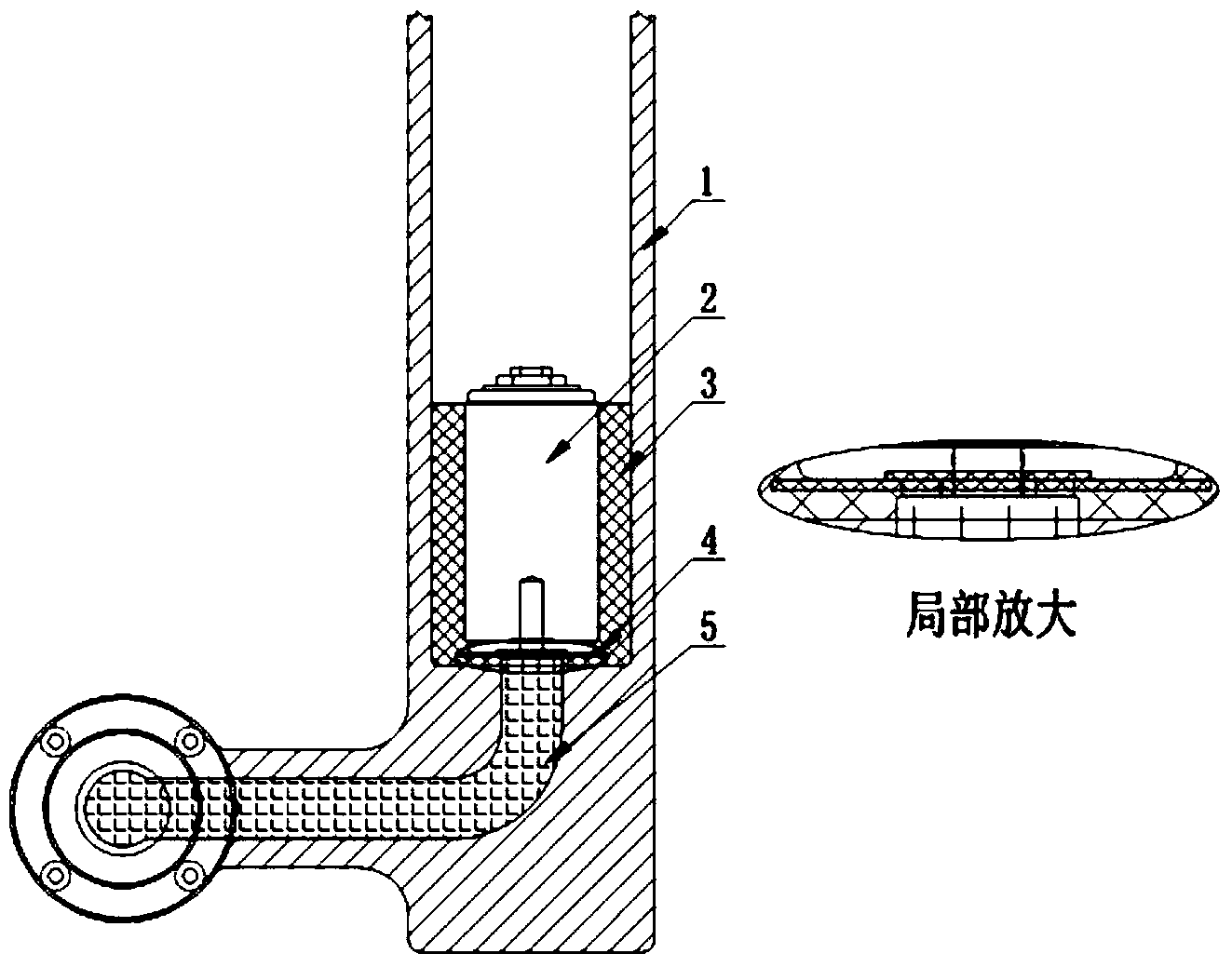
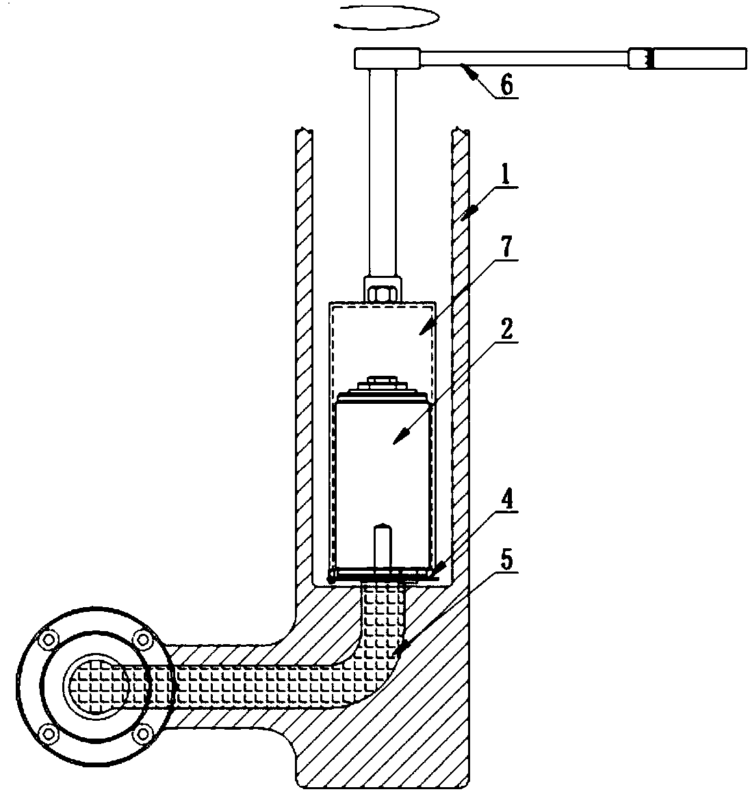
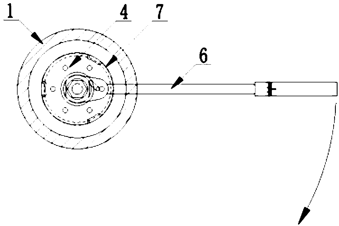
[0019] The present invention will be described in further detail below in conjunction with the accompanying drawings.

[0020] like Figure 1 to Figure 6 As shown, the installation structure of the vacuum switch tube of the present invention includes a specially designed circular plate 4 and a special sleeve 7 . Described circular plate 4 is formed by injection molding of polycarbonate material, and shape is as Figure 5 shown. Polycarbonate has good impact resistance and thermal distortion resistance, and has good weather resistance and high hardness. It will not be deformed or broken under the rotational force of 35-40N, which can meet the installation requirements of the vacuum switch tube 2, and it is a A good flame-retardant and insulating material will not affect the withstand voltage and partial discharge performance of the main body of the cabinet if it is left on the static contact 2-2 of the vacuum switch tube. The shape of the middle part of the circular plate 4 ...


PUM


Abstract

The invention discloses an installing structure for a vacuum switch tube. The installing structure comprises an insulating cylinder, the vacuum switch tube, a circular plate and a special sleeve. A conductor insert is arranged at the bottom of the insulating cylinder, a clamping hole matched with a static contact of the vacuum switch tube is formed in the center of the circular plate, bayonets evenly distributed are formed in the circumference of the circular plate, through holes are formed between the bayonets and the clamping hole, the circular plate is clamped on the static contact of the vacuum switch tube through the clamping hole, and the static contact of the vacuum switch tube is in threaded connection with the conductor insert. Clamping jaws matched with the bayonets of the circular plate are arranged at the bottom of the special sleeve, and a nut is welded to the top of the special sleeve. An installing process for the vacuum switch tube sequentially includes the steps of cleaning tools, installing and preliminarily fastening the circular plate, conducting fastening through the special sleeve and conducting glue filling. Compared with the prior art, the installing structure and the installing process have the advantages that the installing structure is simple and ingenious in design; by the adoption of the process, the sealing performance and glue filling of elements inside the insulating cylinder cannot be affected, and it can be guaranteed that the vacuum switch tube is not damaged.

Description

technical field [0001] The invention relates to an installation process of a vacuum switch tube, in particular to a vacuum switch tube installation structure and its installation process. Background technique [0002] The vacuum switch tube is the core component of the solid insulated ring network cabinet. It is an insulating shell made of glass or ceramics, with a shielding cover, dynamic and static contacts inside, and the dynamic and static contacts are located at both ends of the vacuum switch tube. There is a retractable stainless steel bellows on the cover of the moving contact rod. Its function is to ensure that the vacuum degree of the arc extinguishing chamber is maintained when the moving contact rod moves within a certain range. It is an important part of the vacuum switch tube. When installing a vacuum switch tube in a solid insulated ring network cabinet, if the driven contact end is rotated by force, it may cause damage to the bellows. Only by applying force to...

Claims


Application Information

Patent Timeline
Patent Type & Authority Applications(China)
IPC IPC(8): H01H33/66H01H11/00
Inventor 王育华卢解良
Owner SHANGHAI GDE ELECTRIC
Why Eureka
Try Eureka