Three-clutch gearbox for loader

A three-clutch, gearbox technology, applied in vehicle gearboxes, mechanical equipment, transmission devices, etc., can solve problems such as reducing the service life of gearbox oil, low transmission efficiency of hydraulic torque converters, and affecting the working efficiency of engineering machines. Achieve low shovel loading speed, easy operation, and avoid engine stalling

Inactive Publication Date: 2016-01-20
王云高
View PDF1 Cites 0 Cited by
  • Summary
  • Abstract
  • Description
  • Claims
  • Application Information

AI Technical Summary

Problems solved by technology

Due to the relatively low transmission efficiency of the hydraulic torque converter, the energy consumption is relatively high, and part of the energy consumption is converted into heat during use, which increases the temperature of the gearbox and reduces the service life of the gearbox oil.
[0003] The Chinese invention patent with the authorized announcement number CN102146987B discloses a "engineering machine equipped with a power shift gearbox". Due to its own structural design, there are four defects in use: first, the gearbox must obtain a relatively low Ideal speed requires a large enough transmission ratio
Second, there are also certain restrictions on the speed ratio of the drive axle equipped with the construction machine, and the speed ratio generally does not exceed 1:21.
In order to solve this problem, the meshing delay system is adopted to solve the problem of meshing impact, but the shifting time is prolonged, which affects the working efficiency of the engineering machine

Method used


Image

  • Three-clutch gearbox for loader
  • Three-clutch gearbox for loader
  • Three-clutch gearbox for loader

Examples


Embodiment Construction

[0020] The present invention will be further described below in conjunction with the accompanying drawings and examples.

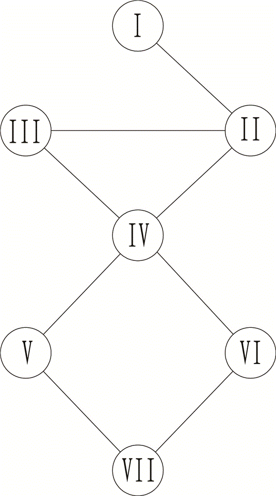
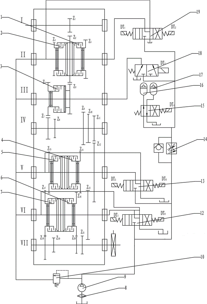
[0021] like figure 1 , 2 As shown, the present invention includes a box, and shafts I, II, III, IV, V, VI and VII are respectively installed in the box through bearings and are parallel to each other. Shaft I is the input shaft, the left end is used to connect with the engine, the right end is connected with the gear pump 9, and the Z1 gear is installed on the shaft I. The first wet clutch 1 and the second wet clutch 2 are installed on the shaft II, and there are lubricating oil passages leading from the left end of the shaft to the friction disc chambers of the first wet clutch 1 and the second wet clutch 2 respectively on the shaft II. There is also a control oil channel leading from the right end of the shaft to the piston chambers of the first wet clutch 1 and the second wet clutch 2 respectively. The third wet clutch 3 is installed on the shaft III...


PUM


Abstract

The invention relates to a three-clutch transmission of a loading machine. The three-clutch transmission comprises a box body, a shaft I, a shaft II, a shaft III, a shaft IV, a shaft V, a shaft VI and a shaft VII, wherein the shaft I, the shaft II, the shaft III, the shaft IV, the shaft V, the shaft VI and the shaft VII are parallel, a first wet clutch (1) and a second wet clutch (2) are arranged on the shaft II, a third wet clutch (3) is arranged on the shaft III, a fourth wet clutch (4) and a fifth wet clutch (5) are arranged on the shaft V, and a sixth wet clutch (6) and a seventh wet clutch (7) are arranged on the shaft VI. Hydraulic clutches replace hydraulic torque converters, so that transmission efficiency is increased, energy consumption is reduced, and automated control is achieved conveniently.

Description

technical field [0001] The invention relates to a three-clutch gearbox of a loader. It is mainly used in loaders with more than two tons. Background technique [0002] At present, the transmission of large and medium-sized loaders generally adopts a hydraulic torque converter plus a power shift transmission. Due to the relatively low transmission efficiency of the hydraulic torque converter, the energy consumption is relatively high, and part of the energy consumption is converted into heat during use, which increases the temperature of the gearbox and reduces the service life of the gearbox oil. [0003] The Chinese invention patent with the authorized announcement number CN102146987B discloses a "engineering machine equipped with a power shift gearbox". Due to its own structural design, there are four defects in use: first, the gearbox must obtain a relatively low Ideal speed requires a large enough transmission ratio. Due to the structure itself, in order to obtain the...

Claims


Application Information

Patent Timeline
Patent Type & Authority Patents(China)
IPC IPC(8): F16H3/08F16H61/40F16H61/04
CPCF16H3/08F16H61/0267F16H61/065F16H2200/0056F16H2200/0095F16H2200/2048
Inventor 王云高王媛媛
Owner 王云高
Why Eureka
Try Eureka