Missile wing gear transmission folding mechanism

A technology of gear transmission and folding mechanism, applied in the direction of gear transmission, transmission, transmission parts, etc., to achieve the effect of good synchronization, small transmission clearance and movement clearance, and small impact force

Inactive Publication Date: 2014-08-06
JIANGXI HONGDU AVIATION IND GRP
View PDF4 Cites 1 Cited by
  • Summary
  • Abstract
  • Description
  • Claims
  • Application Information

AI Technical Summary

Problems solved by technology

However, for new and advanced cruise missiles, due to the demand for voyage, higher requirements are put forward for the missile wings. The traditional left-right symmetrical distributed airfoil can no longer meet the requirements of use. It is necessary to use up and down cross-shaped airfoils to increase the size of the wings. area, increase more lift, and meet the needs of missile range

Method used


Image

  • Missile wing gear transmission folding mechanism
  • Missile wing gear transmission folding mechanism
  • Missile wing gear transmission folding mechanism

Examples


Embodiment

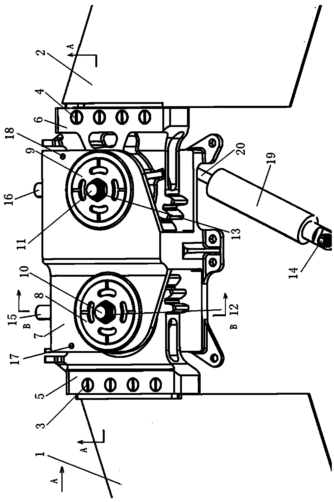
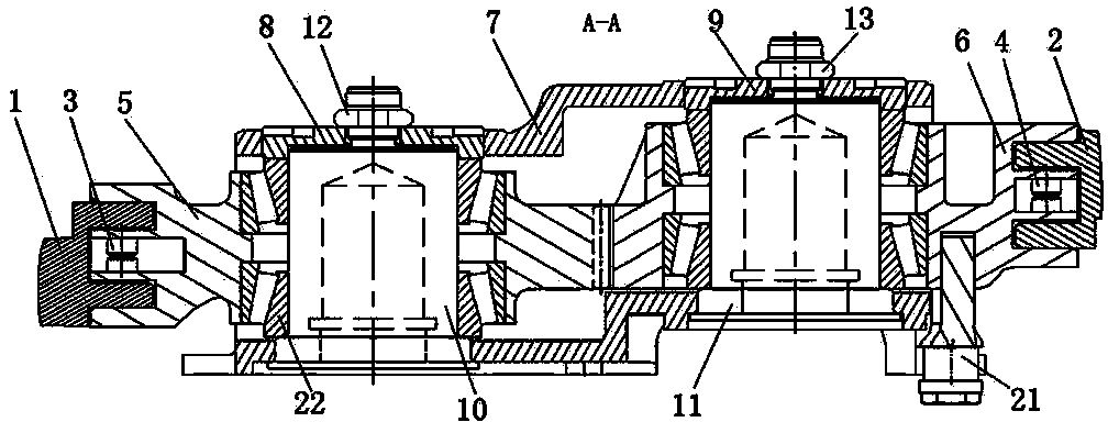
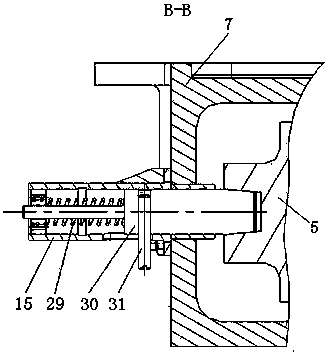
[0023] Example: see figure 1 ——5.

[0024] In the figure, 1 is the left elastic wing, 2 is the right elastic wing, 3 is a fastener, 4 is a fastener, 5 is a left gear joint, 6 is a right gear joint, 7 is a gear box, 8 is a left screw sleeve, 9 is the right threaded sleeve, 10 is the rotating shaft of the left elastic wing, 11 is the rotating shaft of the right elastic wing, 12, 13 are left and right self-locking nuts, 14 are hinge bolts, 15, 16 are left and right spring locking pins, 17, 18 19 is a driving device, 20 is a piston, 21 is a connecting pin, 22 is a tapered roller bearing, 23, 24, 25, 26, 27, and 28 are connecting angle pieces, 29 is a spring, and 30 is a pin head, 31 is the locking bolt,

[0025] The invention discloses a wing gear transmission folding mechanism, which comprises a gear box 7, in which a left gear joint 5 and a right gear joint 6 engaged with each other are arranged, the left end of the left gear joint 5 and the right end of the right gear joint 6...


PUM


Abstract

The invention relates to the technical field of design of missile structures, in particular to a missile wing gear transmission folding mechanism. The missile wing gear transmission folding mechanism comprises a gear box, a left gear connector and a right gear connector are arranged in the gear box, the left gear connector and the right gear connector are meshed with each other, the left end of the left gear connector and the right end of the right gear connector are both located outside the gear box and are connected with a left missile wing and a right missile wing respectively, the left gear connector and the right gear connector are arranged outside a left missile wing rotating shaft and a right missile wing rotating shaft respectively through a conical roller bearing in a sleeved mode, a connecting pin is arranged at the lower end of the right gear connector, the connecting pin is connected with a driving device, the right gear connector and the left gear connector are driven to rotate through the driving device, and therefore the two missile wings are driven to rotate. The missile wing gear transmission folding mechanism is simple, reliable and convenient to fold, disassemble and assemble.

Description

technical field [0001] The invention relates to the technical field of missile structure design, in particular to a wing gear transmission and folding mechanism. Background technique [0002] The increasing complexity of the war environment requires the missiles to have smaller and smaller lateral dimensions in order to facilitate box-type storage, transportation and launch, save storage space for missiles, increase the storage and transportation capacity of storage and transportation devices, and thus improve the combat capability of weapon systems . [0003] In order to solve the problem of less storage and transportation of missiles per unit space, the technology of folding wings has been applied at home and abroad. Most of them adopt longitudinal folding, and the wings are symmetrically distributed. The typical folding mechanism is Y-shaped single and double guide (sliding) rails. The connecting rod unfolding mechanism uses a single slider to push (pull) two connecting ...

Claims


Application Information

Patent Timeline
IPC IPC(8): F16H1/06F16H57/00
CPCB64C1/26F42B15/01
Inventor 邓进刘慧慧陈雷皇东亚孙启星李雁飞孙英超胜永民
Owner JIANGXI HONGDU AVIATION IND GRP
Why Eureka
Try Eureka