
Cylinder cover used for internal combustion engine

An internal combustion engine and cylinder head technology, applied in the direction of engine cooling, engine components, machines/engines, etc., can solve the problems of excessive heating of the cylinder head, weakening of the sealing effect of the cylinder head and the supercharger, and achieve the effect of ensuring the sealing performance

Inactive Publication Date: 2014-08-06
HONDA MOTOR CO LTD
View PDF4 Cites 4 Cited by
  • Summary
  • Abstract
  • Description
  • Claims
  • Application Information

AI Technical Summary

Problems solved by technology

Also, the distance between the exhaust confluence and the supercharger is so small that the cylinder head may be overheated and the sealing effect between the cylinder head and the supercharger may be weakened due to deformation of the surrounding parts

Method used


Image

  • Cylinder cover used for internal combustion engine
  • Cylinder cover used for internal combustion engine
  • Cylinder cover used for internal combustion engine

Examples


no. 1 approach

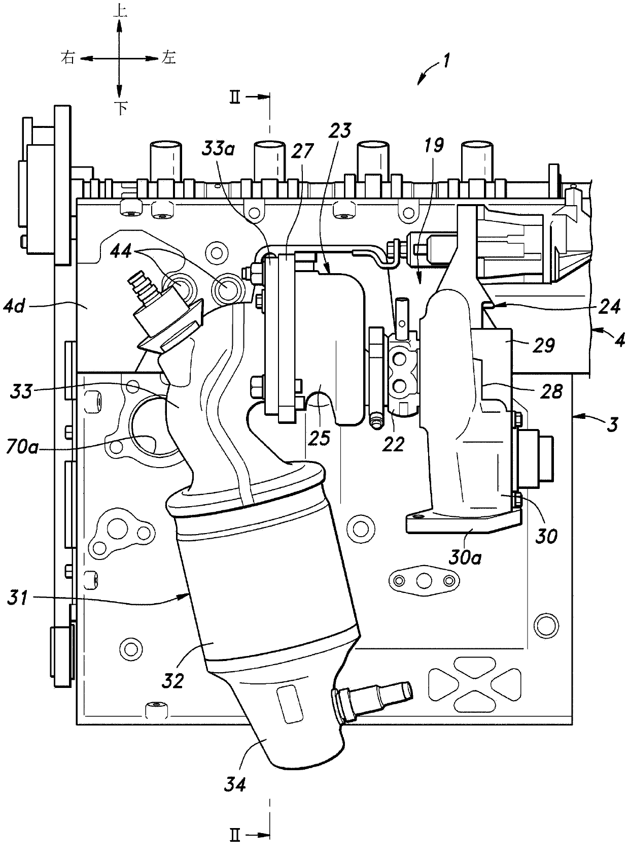
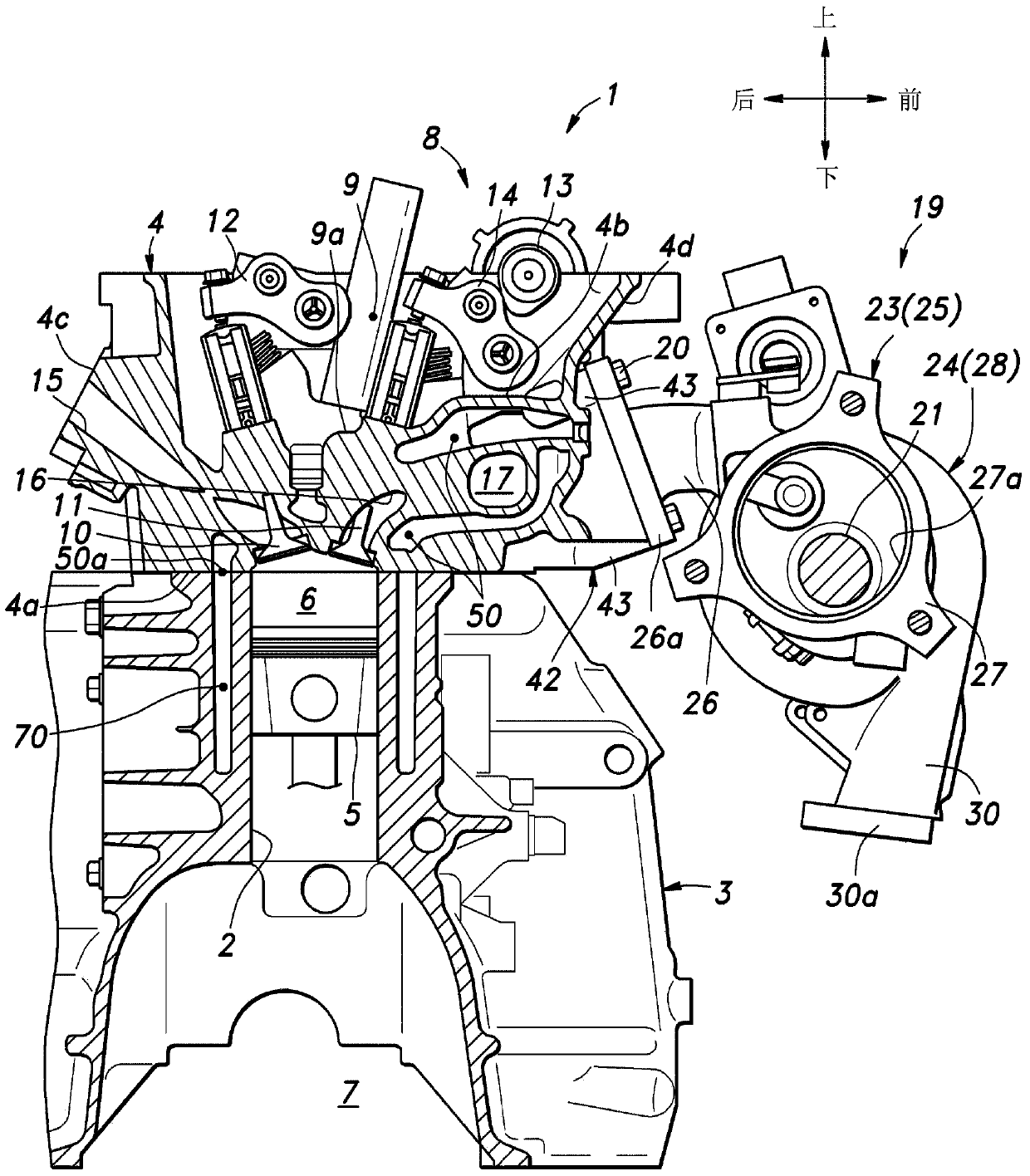
[0044] Such as figure 1 and figure 2 As shown, the engine 1 is mainly composed of a DOHC four-valve inline four-cylinder engine, and includes a cylinder block 3 defining four cylinder bores 2 arranged in a row, and a box-shaped cylinder head 4 attached to the upper surface of the cylinder block 3 , the cylinder head extends perpendicular to the cylinder bore 2 . The cylinder block 3 and the cylinder head 4 are made of die-cast aluminum alloy.

[0045] In the following description, it is assumed that the engine is oriented such that the axis of each cylinder bore 2 (cylinder axis) extends in a vertical vertical direction, and that the exhaust side of the laterally placed engine 1 faces forward. However, the actual orientation of the engine 1 when mounted on a vehicle is not limited by this example. In the following description, for the convenience of description, the vertical direction and the front-to-back direction are defined based on this orientation of the engine 1. ...

no. 2 approach

[0108] The following will refer to Figure 18 and Figure 19 A second embodiment of the present invention will be described. exist Figure 18 and Figure 19 In , parts corresponding to those in the first embodiment are designated by like reference numerals, and it is not necessary to repeat description of these parts in the corresponding written description.

[0109] In this embodiment, if Figure 18 As shown, the cooling water inlet 50a of the cylinder head water jacket 50 is more preferably provided on the intake side of each combustion chamber 6 or on the intake side of the main water jacket 51 to a more pronounced extent than in the first embodiment. More specifically, the cooling water inlets 50a arranged on the exhaust side are less and / or smaller than the cooling water inlets 50a arranged on the intake side. That is, the cooling water inlet 50 a is offset toward the intake side of the main water jacket 51 . The expression that the cooling water inlet 50a is "prefe...


PUM


Abstract

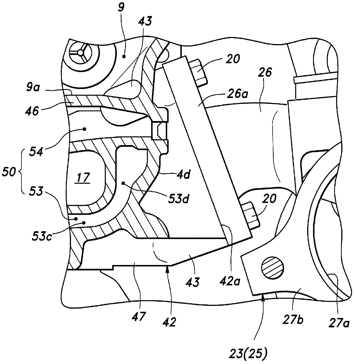
The invention provides a cylinder cover used for an internal combustion engine (1). The cylinder cover is internally provided with an exhaust covergence part (17), thereby preventing the size of the cylinder cover from being too large while preventing thermal dformation of a part surrounding an outlet end of the exhaust convergence part. An exhaust outlet (18) of the exhaust convergence part (17) is defined by an exhaust outlet tubular part, the exhaust outlet tubular part protrudes from a side face of the cylinder cover (4), the exhaust outlet tubular part (42) is away from a combustion chamber and is inclined upwards, and a free end of the exhaust outlet tubular part has a mounting surface (42a) used for being connected with a supercharger(19) or a connecting pipe that leads to the supercharger. A lower exhaust water jacket (53) extends from a part (a tongue-shaped part (53e)) which covers the exhaust covengence part (17) at a lower side and enters into a lower wall (42b) of the exhaust outlet tubular part (42).

Description

technical field [0001] The present invention relates to a cylinder head for an internal combustion engine having an exhaust gas confluence portion defined therein. Background technique [0002] In a conventional multi-cylinder engine, a plurality of intake ports and exhaust ports are defined in the cylinder head such that they open on the intake side surface and the exhaust side surface of the cylinder head, respectively, and are used to distribute the intake air An intake manifold and an exhaust manifold for merging exhaust gas are respectively attached to the intake side surface and the exhaust side surface of the cylinder head. Recently, an exhaust merging portion for merging exhaust gas is sometimes defined within the cylinder head so that a separate exhaust pipe is connected to the exhaust side surface of the cylinder head. [0003] In a multi-cylinder engine with an exhaust gas confluence defined within the cylinder head, the overall size of the engine can be reduced ...

Claims


Application Information

Patent Timeline
IPC IPC(8): F02F1/42F02F1/36F02F1/24
CPCF02F1/40F01P3/02F01P2003/024F01P2060/16F02F2001/4278
Inventor 多田和司桥本明典
Owner HONDA MOTOR CO LTD
Learn More