Side face snow plow for land leveller

一种平地机、雪犁的技术,应用在雪面清洗、移土机/挖土机、机械驱动的挖掘机/疏浚机等方向,能够解决不稳、重心前移、路面伤害等问题,达到增加单程除雪宽度、避免重心前倾、减少打滑的效果

Active Publication Date: 2014-08-06
XUZHOU XUGONG ROAD CONSTR MACHINERY
View PDF6 Cites 8 Cited by
  • Summary
  • Abstract
  • Description
  • Claims
  • Application Information

AI Technical Summary

Problems solved by technology

At present, there are various snow removal devices suitable for installation on motor graders, such as "one" shape and "V" shape, such as the Chinese invention patent disclosed on April 24, 2013, publication number CN103061299A, these snow removal devices are all Installed on the front frame of the motor grader, this results in a large overlapping area between the snow removal area and the blade, and cannot increase the actual snow removal width of the motor grader
[0004] When clearing snow, the blade needs to be as close as possible to the road surface, so as to ensure better snow removal quality, and the road surface will inevitably have raised hard objects, such as cracks on the road surface, bumps after road repair, etc. These bumps will give The blades cause a lot of damage; and this snow removal method will also cause a lot of damage to the road surface
[0005] As we all know, the motor grader is mainly driven by the rear wheels. Due to the long body of the motor grader, generally speaking, 70% of the weight of the motor grader is loaded on the rear wheels. This structure with a light front and a heavy rear can be more stable on wet and slippery roads , if the snow removal device is installed at the front end of the motor grader, it must cause the center of gravity to move forward. Due to the wet and slippery ice and snow road, it is easy to cause slipping and instability. Secondly, the snow removal device is installed at the front end and blocks the driver's forward direction.

Method used


Image

  • Side face snow plow for land leveller
  • Side face snow plow for land leveller
  • Side face snow plow for land leveller

Examples


Embodiment Construction

[0020] The present invention will be further described below in conjunction with accompanying drawing.

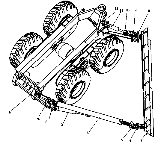
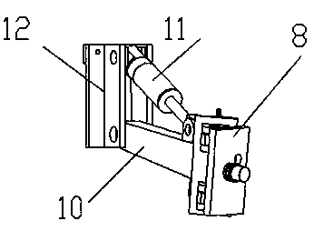
[0021] like figure 1 As shown, the side snow plow for a motor grader of the present invention includes a rear mounting seat 1, a hydraulic cylinder I3, a tie rod body 4, a snow pusher 7, a swing rod 10, a hydraulic cylinder II11 and a front mounting seat 12; the rear mounting seat 1 is fixed on At the rear end of the rear frame of the motor grader, the rear mounting seat 1 is hinged to the hinge plate I2 through the pin shaft 9; one end of the tie rod body 4 is hinged to the hinge plate I2 through the pin shaft, and the other end is hinged to the hinge plate II6 through the fixed pin shaft 5; One end of the oil cylinder I3 is hinged with the rear mounting base 1, and the other end is hinged with the tie rod body 4; the front mounting base 12 is fixed at the front end of the rear frame of the motor grader; There is a hinged plate III8; one end of the hydraulic cylinder II11...


PUM


Abstract

The invention discloses a side face snow plow for a land leveller. The side face snow plow for the land leveller comprises a rear mounting base, a hydraulic cylinder I, a drag link body, a snow pushing plate, an oscillating rod, a hydraulic cylinder II and a front mounting base. The rear mounting base is fixedly arranged at the rear end of a rear rack of the land leveller. One end of the drag link body is connected to a hinged plate I through a hinge pin, and the other end of the drag link body is connected to a hinged plate II through a fixing hinge pin. One end of the hydraulic cylinder I is hinged to the rear mounting base, and the other end of the hydraulic cylinder I is hinged to the drag link body. The front mounting base is fixedly arranged at the front end of the rear rack of the land leveller. One end of the oscillating rod is hinged to the front mounting base, and the other end of the oscillating rod is connected with a hinge plate III in a hinged mode through a hinge pin. One end of the hydraulic cylinder II is hinged to the front mounting base, and the other end of the hydraulic cylinder II is hinged to the oscillating rod. The snow pushing plate is placed on the left side or the right side of the land leveller and tilts towards the forward moving direction of the land leveller, the rear end of the snow pushing plate is connected to the hinged plate II, and the front end of the snow pushing plate is connected to the hinged plate III. During snow removing operation, the efficiency of snow removing operation is improved, the view field of a driver cannot be shielded, and thus road surface obstacles can be effectively avoided.

Description

technical field [0001] The invention relates to a snow plow device for engineering vehicles, in particular to a side snow plow for graders, which belongs to the technical field of engineering machinery applications. Background technique [0002] As a snow removal tool, the motor grader has the following characteristics: wide application range, small snow removal operation space, high snow removal operation speed, and strong adaptability. However, there is a certain gap between its snow removal efficiency and that of professional snow removal machines. However, the price of dedicated large-scale snow removal machines is higher, and the annual idle period is longer, which will inevitably lead to waste of resources. [0003] In recent years, more and more areas like to use graders for snow removal operations, some use special snow removal devices, and some directly use the blade of the grader for snow removal operations. At present, there are various snow removal devices suita...

Claims


Application Information

Patent Timeline
Patent Type & Authority Applications(China)
IPC IPC(8): E02F3/80E01H5/06
CPCE01H5/067E02F3/7677E02F3/7681E02F3/7686
Inventor 宋宗华戚洪强卢圣利孟庆轩何菊段俊杰范杨张强大熊聪陈超海龚广东
Owner XUZHOU XUGONG ROAD CONSTR MACHINERY
Why Eureka
Try Eureka