
Drive device having an electrical drive machine

A driving device and driving machine technology, applied in the direction of electric power device, power device, transmission device, etc., can solve the problem of large structural space and achieve the effect of simple structural design and good support

Inactive Publication Date: 2014-07-30
SIEMENS AG
View PDF5 Cites 0 Cited by
  • Summary
  • Abstract
  • Description
  • Claims
  • Application Information

AI Technical Summary

Problems solved by technology

In conventional drives, a large installation space is required because the transmission is connected to the drive outside the drive machine

Method used


Image

  • Drive device having an electrical drive machine
  • Drive device having an electrical drive machine

Examples


Embodiment Construction

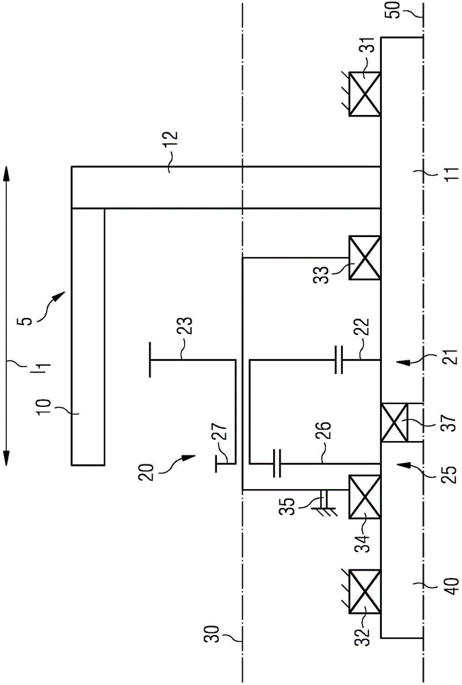
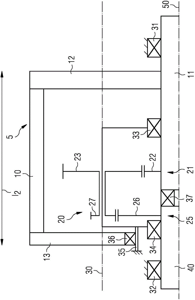
[0021] figure 1 A first embodiment of the drive device according to the invention is shown. The drive device is provided in particular as a drive machine for a vehicle, for example a purely electric drive or a combined electric internal combustion engine drive (hybrid vehicle). The drive can of course also be used in other applications, especially when a conversion of the rotational speed is required.

[0022] The drive includes an electric drive machine 5 , not further shown. The electric drive machine comprises a rotor 10 in a known manner, which is connected to a rotor shaft 11 in a rotationally fixed manner, for example via a rotor flange 12 . The electric drive machine 5 , like the remaining components of the drive described further below, is only half shown in each case with respect to the axis of rotation 50 . The stator of the electric drive machine 5 , with respect to which the rotor shaft 11 is located above and outside the rotor 10 , is not explicitly shown. The...


PUM


Abstract

The invention describes a drive device, in particular for a vehicle, having an electrical drive machine (5), which is coupled to a drive axle by means of a gear arrangement (20). The gear arrangement (20), comprising a gear mechanism and / or a differential, is integrated within the rotor (10) of the electrical drive machine (5).

Description

technical field [0001] The invention relates to a drive, in particular for a vehicle, with an electric drive machine coupled to a drive shaft via a transmission arrangement. Background technique [0002] The transmission device of the drive is used to convert the rotational speed of the electric drive machine into the rotational speed of the electric drive shaft. The transmission device usually includes a transmission and / or a differential for comparing the different wheel speeds of the left and right wheels of the drive shaft. In conventional drives, a relatively large installation space is required, since the transmission device is connected to the drive outside the drive machine. Especially in the case of use in vehicles, the drive is accommodated in the narrowest installation space, so there is a need for a drive with an optimized installation space. Contents of the invention [0003] It is an object of the invention to provide a drive device which can be provided wi...

Claims


Application Information

Patent Timeline
Patent Type & Authority Applications(China)
IPC IPC(8): B60K1/00F16H1/00
CPCB60K1/00B60K2001/001B60Y2304/01F16H1/22B60K17/12
Inventor 弗兰克·博伊尔莱因马库斯·克勒普兹格克劳斯·施莱克尔
Owner SIEMENS AG
Learn More