Computer simulation testing system for high voltage direct current transmission equipment

A technology of high-voltage direct current transmission and computer simulation, which is applied in the field of test systems, can solve problems such as the inability to reflect the action of the thyristor level, the inability to effectively simulate the fault on the valve side of a single valve failure, and the inability to accurately reflect the action response of the TTM board, etc., to ensure realism effect

Active Publication Date: 2014-07-30
STATE GRID CORP OF CHINA +2
View PDF2 Cites 21 Cited by
  • Summary
  • Abstract
  • Description
  • Claims
  • Application Information

AI Technical Summary

Problems solved by technology

[0013] In the prior art, the power system RTDS of the high-voltage direct current transmission project before it is put into operation is not connected to the actual thyristor level and the simulation return link. The usual test wiring is composed of VBE, RTDS, and direct current transmission control and protection system. The simulation of the valve side is realized by modifying the software in VBE, which cannot accurately reflect the action response of the TTM board (thyristor trigger monitoring board) and the thyristor level to the control protection command and trigger pulse, especially the thyristor level. When the control signal is abnormal, it cannot effectively simulate valve side faults such as single valve failure

Method used


Image

  • Computer simulation testing system for high voltage direct current transmission equipment
  • Computer simulation testing system for high voltage direct current transmission equipment

Examples


Embodiment Construction

[0031] The present invention will be described in further detail below in conjunction with the accompanying drawings.

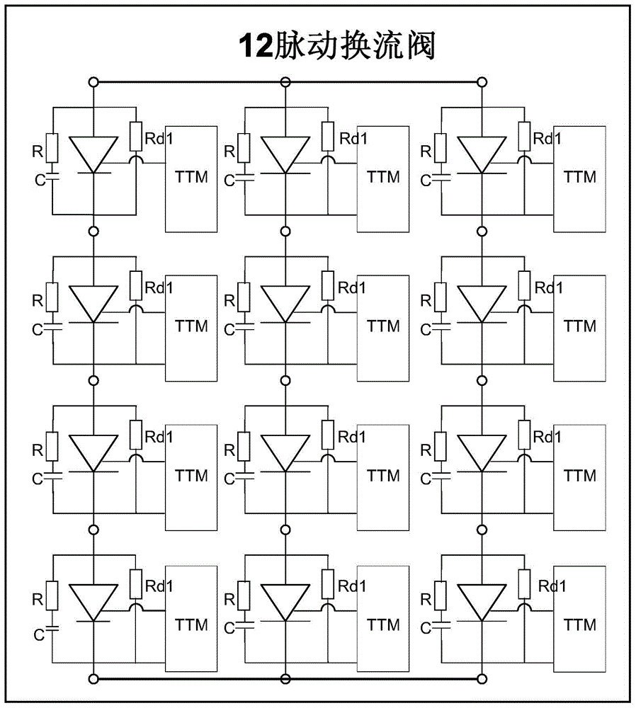
[0032] The invention provides a new type of computer simulation test device for HVDC transmission equipment, which is designed to meet the VBE and TTM of HVDC transmission equipment for RTDS (real-time digital simulation) test, and its main function is to simulate the actual high voltage Triggering and monitoring systems for HVDC converter valves and operating status of thyristor stages. Due to the large volume of the converter valve tower of the main HVDC power transmission main equipment, the 12-pulse converter valve tower involves a lot of thyristor stages, the actual physical size is tens of meters high, and the operating voltage is as high as hundreds of kilovolts. The equipment investment is extremely high, only The test verification can only be carried out after the converter station is built. The test device of the present invention uses RTDS to simu...


PUM


Abstract

The invention provides a computer simulation testing system for high voltage direct current transmission equipment. The computer simulation testing system for the high voltage direct current transmission equipment comprises a control protection system, a valve base electronic cabinet, a simulation return cabinet, a converter valve cabinet, an RTDS interface device and a real-time data simulation system. The control protection system is used for transmitting 12-path triggering signals to the valve base electronic cabinet, the valve base electronic cabinet is used for transmitting TTM board single-double pulse driving signals to the converter valve cabinet through the simulation return cabinet, and the RTDS interface device is used for transmitting terminal voltage signals for pulsing converter valves to the converter valve cabinet and supplying power to TTM boards inside the converter valve cabinet. According to the computer simulation testing system for the high voltage direct current transmission equipment, an RTDS is used for simulating the operation of a power system, the converter valve cabinet is used for simulating the converter valves, the expansion of the series of thyristors of the converter valves is achieved through the simulation return cabinet, in this way, a high voltage direct current transmission converter valve tower is equivalently reduced to the size of four standard electric screen cabinets, simulation testing can be conducted in a computer simulation laboratory, and the performance verification of valve base electronic equipment and TTMs and the test verification of direct current transmission control strategies and methods can be achieved.

Description

technical field [0001] The invention relates to a test system, in particular to a computer simulation test system for high-voltage direct current transmission equipment. Background technique [0002] HVDC transmission technology is used for long-distance transmission of electric energy through overhead lines and submarine cables; at the same time, it is also used for the connection between independent power systems in some occasions where traditional AC connection is not suitable. The world's first commercial high-voltage direct current transmission line was born in Sweden in 1954 to connect the mainland of Sweden and Gotland, and was completed by ASEA (now ABB Group). [0003] In a HVDC transmission system, electric energy is derived from one point of the three-phase AC grid, converted into DC at the converter station, and transmitted to the receiving point through overhead lines or cables; after the DC is converted into AC at the other side of the converter station, it is ...

Claims


Application Information

Patent Timeline
IPC IPC(8): H02J3/36G06F17/50
CPCY02E60/60
Inventor 陈龙龙周亮郝长城林志光王华锋
Owner STATE GRID CORP OF CHINA
Why Eureka
Try Eureka