Foldable type hydraulic hoisting frame

A hydraulic lifting and folding technology, which is applied in the direction of lifting frames and lifting devices, can solve the problems of no fundamental improvement in overall rigidity and stability, high space utilization, and high overall rigidity of equipment, so as to achieve full utilization of the crank arm length and layout Small footprint and high space utilization

Inactive Publication Date: 2014-07-30
毕和军
View PDF4 Cites 3 Cited by
  • Summary
  • Abstract
  • Description
  • Claims
  • Application Information

AI Technical Summary

Problems solved by technology

Due to the impact of the structure, the improvement of equipment material, manufacturing process and precision has no fundamental improvement in its overall rigidity and stability
[0005] The performance of the cylinder type sliding arm lifting platform is similar to that of the scissor lifting platform, and it also has the characteristics of low utilization rate of the length of the lifting arm, low overall rigidity of the equipment and low stability at high altitude.
[0006] The single-arm folding arm lifting platform has a large lifting height and a high utilization rate of the lifting arm length, but its bearing capacity, overall rigidity, and platform stability are low. It is suitable for carrying people on high for maintenance or lifting and installation of light products.
[0007] The above-mentioned existing types of lifting platforms cannot simultaneously meet the comprehensive performance requirements of large lifting height, large lifting force, high overall rigidity of the equipment, good high-altitude stability, high space utilization rate, and ease of movement.

Method used


Image

  • Foldable type hydraulic hoisting frame
  • Foldable type hydraulic hoisting frame
  • Foldable type hydraulic hoisting frame

Examples


Embodiment Construction

[0043] 1. According to different usage requirements, the lifting frame can be designed into the following types:

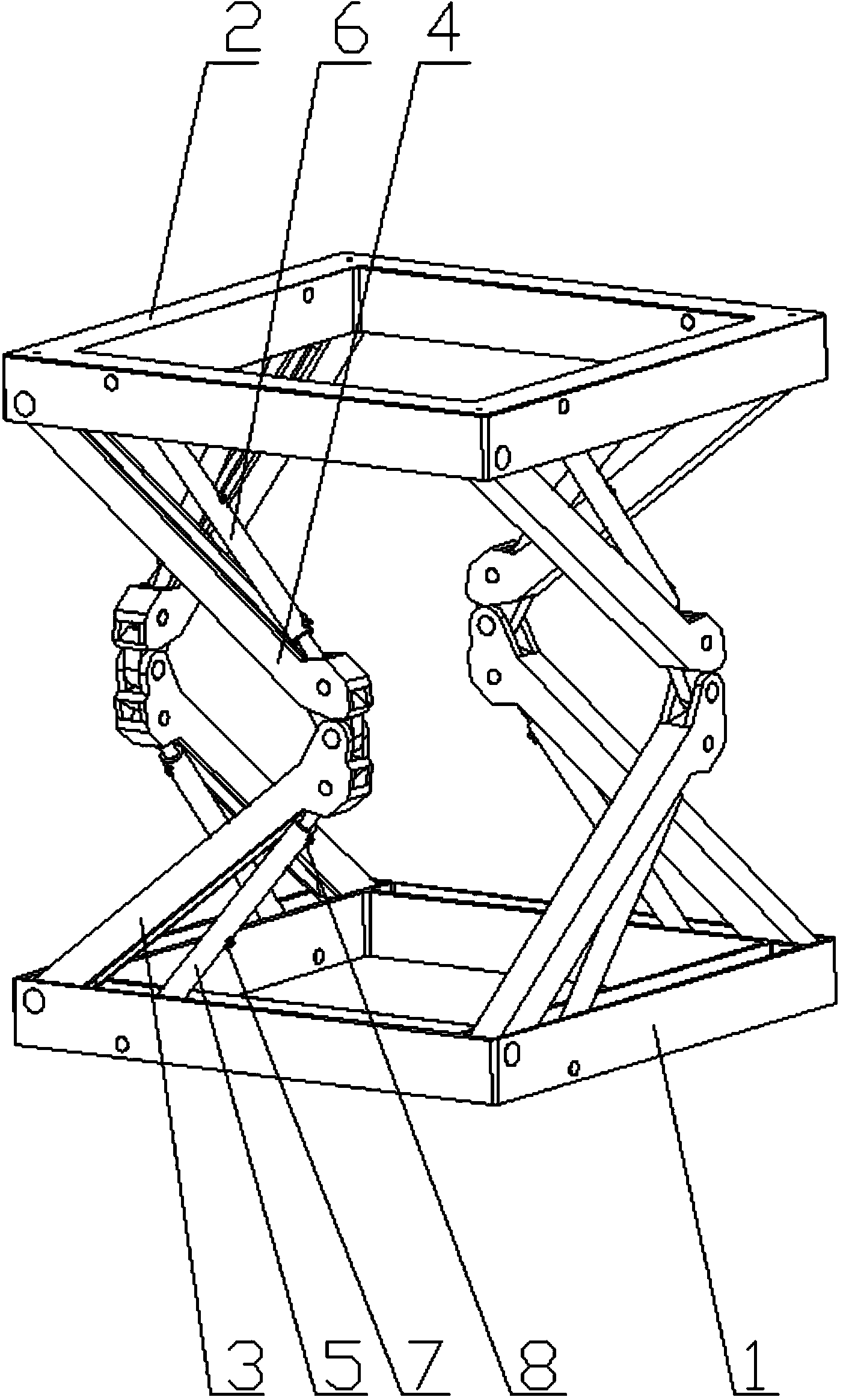
[0044] 1. Crank arm side bending lifting frame, such as figure 1 shown. Its characteristics are:

[0045] Use three or more sets of lifting crank arms, the bending direction of the crank arms is the same counterclockwise direction or the same clockwise direction or a lateral staggered direction, the end of the piston rod of the upper lifting hydraulic cylinder 6 is hinged to the lower part of the upper crank arm 4 , the end of the piston rod of the lower lift hydraulic cylinder 5 is hinged with the upper part of the lower crank arm 3 .

[0046] 2. The curved arm is opposite to the radial bending lifting frame, such as Figure 5 shown. Its characteristics are:

[0047] Three or more pairs of lifting crank arms are used, and the bending direction of the crank arms is opposite radial. The crank arm 3 top is hinged.

[0048] 3. Parallel-to-bending lifting frame...


PUM


Abstract

The invention discloses a foldable type hydraulic hoisting frame. The foldable type hydraulic hoisting frame comprises an upper-layer hoisting platform and a lower-layer hoisting platform, at least two pairs of hoisting crank arms, and hoisting hydraulic cylinders which are correspondingly matched with the hoisting crank arms; each hoisting crank arm is composed of the lower end of an upper crank arm and the upper end of a lower crank arm by hinging; the upper-layer hoisting platform is connected with the lower-layer hoisting platform by the hoisting crank arms; each hoisting hydraulic cylinder comprises an upper-layer hoisting hydraulic cylinder and a lower-layer hoisting hydraulic cylinder; each upper-layer hoisting hydraulic cylinder is provided with a gear pump; each upper-layer hoisting hydraulic cylinder and the adjacent upper-layer hoisting hydraulic cylinder on the same layer form oil path connection through a configured gear pump; all the upper-layer hoisting hydraulic cylinders on the same layer form end-to-end circulating connection through the respective configured gear pump. According to the foldable type hydraulic hoisting frame, the gear pumps for forming the oil path connection between the hoisting hydraulic cylinders on the same layer drive hydraulic oil in a sealed oil path to carry out inner flowing; the crank arms on the same layer can realize synchronous balance and linked folding opening and closing, so that the aim of hoisting the hoisting frame in a balanced and stable manner is realized.

Description

technical field [0001] The invention relates to the field of lifting machinery, in particular to a folding hydraulic lifting frame. Background technique [0002] At present, the known hydraulic lifting systems mainly include hydraulic cylinder direct lifting platform, scissor hydraulic lifting platform, cylinder sleeve type sliding arm lifting platform and single arm folding arm lifting platform and other types. [0003] The hydraulic cylinder direct lifting platform has strong lifting capacity, and the lifting height is limited by the length of the hydraulic cylinder. It is suitable for industrial lifting operations with small worktables, short strokes, and fixed locations, and is not suitable for high-altitude operations. [0004] The lifting height of the scissor hydraulic lifting platform is higher than that of the hydraulic cylinder direct lifting platform, which can be used for mobile operations such as loading, installation, and maintenance. Due to the limitations of...

Claims


Application Information

Patent Timeline
Patent Type & Authority Applications(China)
IPC IPC(8): B66F7/08
Inventor 毕和军
Owner 毕和军
Why Eureka
Try Eureka