Automatic pneumatic punching machine

A pneumatic punching machine and automatic technology, applied to punching machines, presses, manufacturing tools, etc., can solve the problems of cost waste, high punching force, and high purchase cost of punching machines, and achieve the effects of reducing production costs, low cost, and energy saving

Inactive Publication Date: 2014-07-30
ANHUI MENGLING PRECISION ELECTRONICS
View PDF7 Cites 2 Cited by
  • Summary
  • Abstract
  • Description
  • Claims
  • Application Information

AI Technical Summary

Problems solved by technology

[0003] Among them, with the development of the gasket industry, some plastic or paper gaskets will be produced. The traditional punch presses are expensive to purchase and the punching force is large. When applied to the production process of plastic or paper gaskets, a certain amount of cost is wasted, and the use is restricted. Limitations

Method used


Image

  • Automatic pneumatic punching machine

Examples


Embodiment Construction

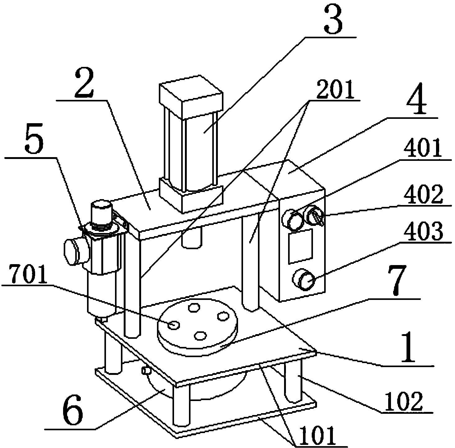
[0014] Referring to the accompanying drawings, an automatic pneumatic punching machine includes a base 1, a frame 2, a stamping mechanism 3, a workbench 7 and a control box 4, and is characterized in that: the stamping mechanism 3 is a cylinder, and the cylinder is inverted on the frame 2 On the crossbeam, the base 1 is a sandwich mechanism supported by two metal plates 101 through a number of support rods 102. A rotating cylinder 6 is installed in the middle of the interlayer, and the rotating cylinder 6 is connected to the workbench 7. On the frame 2 An air valve 5 is provided; the frame 2 is installed on the base 1 as a crossbeam through the support rods 201 on both sides; Stop switch 403; the workbench 7 is a circular workbench, and the workbench is provided with some installation holes 701; the two metal plates 101 of the base 1 are square, and the support rods 102 are 4, and the support rods support respectively at the corner of the sheet metal.


PUM


Abstract

The invention discloses an automatic pneumatic punching machine which overcomes defects in the prior art and is reasonable in design and structure. A punching mechanism is an air cylinder; a rotary workbench is controlled by a rotating air cylinder; after the punching air cylinder accomplishes punching for one time, the rotating air cylinder controls the rotary workbench to carry out indexing rotation for one time; a product to be punched is rotated to a punching area; a punched product is rotated out; the product to be punched and the punched product are converted via the rotary workbench; and when the punching air cylinder works continuously, a worker accomplishes auxiliary work in an area beyond the punching area.The machine overcomes the defects in the prior art and is reasonable in design and structure; the punching mechanism is in an air cylinder structure, so that the machine is convenient to maintain, high in safety coefficient and low in manufacturing cost; at the same time, with the adoption of pneumatic control, no pollution is caused; a working environment is clean; energy is saved; production cost is lowered; and an application scope is wide.

Description

technical field [0001] The invention relates to the technical field of punching machines, in particular to an automatic pneumatic punching machine. Background technique [0002] Punching machines are mainly for plates in production. Through the mold, blanking, punching, forming, deep drawing, trimming, fine blanking, shaping, riveting and extrusion parts can be made, which are widely used in various fields. For example, we use switch sockets, cups, cupboards, plates, computer cases, and many accessories can be produced by punching through molds. [0003] Among them, with the development of the gasket industry, some plastic or paper gaskets will be produced. The traditional punch presses are expensive to purchase and the punching force is large. When applied to the production process of plastic or paper gaskets, a certain amount of cost is wasted, and the use is restricted. limitations. Contents of the invention [0004] The purpose of the present invention is to provide...

Claims


Application Information

Patent Timeline
Patent Type & Authority Applications(China)
IPC IPC(8): B30B1/38
Inventor 钱胜利凌巧
Owner ANHUI MENGLING PRECISION ELECTRONICS
Why Eureka
Try Eureka