Automatic stop finger mechanism of bending machine

A bending machine and automatic transmission technology, applied in the field of bending machines, can solve the problems of low positioning accuracy, unfavorable precise fine-tuning, cost overturning, etc., to achieve the effect of ensuring processing quality, improving positioning accuracy, and ensuring positioning accuracy

Active Publication Date: 2014-07-30
诸暨市英帕斯机械有限公司
View PDF6 Cites 1 Cited by
  • Summary
  • Abstract
  • Description
  • Claims
  • Application Information

AI Technical Summary

Problems solved by technology

The manual Z-axis mechanism is currently the most widely used, but it needs to manually enter the working area of ​​the back gauge mechanism to manually adjust the position, which has the risk of work-related injuries, and the positioning accuracy is low
Although the servo Z-axis mechanism reduces the risk of industrial accidents for workers and improves positioning accuracy and digital control, the cost has increased several times, and most customers do not approve of such a cost.
[0004] Moreover, the back of the finger does not have a fine-tuning function, and the front surface is generally designed to be in one-plane contact, which is not conducive to the adjustment of the finger and the zero point of the machine tool during the debugging process, and it is even more unfavorable to realize the precise fine-tuning function

Method used


Image

  • Automatic stop finger mechanism of bending machine
  • Automatic stop finger mechanism of bending machine
  • Automatic stop finger mechanism of bending machine

Examples


Embodiment Construction

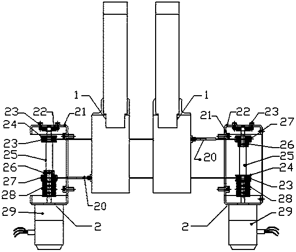
[0023] Such as figure 1 As shown, an automatic finger locking mechanism for a bending machine includes finger driving devices 2 arranged on the left and right sides of the bending machine. Finger 1, the finger 1 is slidably arranged on the Z-axis slide rail of the bending machine, and is driven by the finger drive device 2 to move left and right along the Z-axis slide rail.

[0024] Such as figure 1 As shown, specifically, the finger driving device 2 includes a driving base 21, the driving base 21 has an approximate U-shaped structure, and the driving shaft 25 is vertically and rotatably installed on the driving base 21, and the driving shaft 25 is driven by Driven by a motor 29, the driving shaft is axially equipped with a driving wheel 26 and a driven wheel 24, the driving wheel and the driving shaft are fixed, a bearing 23 is arranged between the driven wheel and the driving shaft, and the driving shafts on the left and right sides The upper driving wheel and the driven w...


PUM


Abstract

The invention discloses an automatic stop finger mechanism of a bending machine, which comprises stop finger drive devices arranged on the left side and the right side of the bending machine, wherein a pair of stop fingers is arranged side by side between the stop finger drive devices on the left side and the right side; drive shafts are axially equipped with driving wheels and driven wheels; the driving wheels are fixed with the drive shafts; drive belts are arranged between the driving wheels and the driven wheels on the drive shafts on the left side and the right side; the two drive belts are fixed with the two stop fingers respectively and drive the two stop fingers to move between the left side and the right side respectively; stop finger fore-and-aft fine adjustment devices for adjusting fore-and-aft positions of stop finger bases in slide grooves are arranged on stop finger slide blocks; the front end of each stop finger base is connected with a front stop finger via a floating pin shaft; and horizontal adjustment device for adjusting horizontal positions of the front stop fingers are arranged on the stop finger slide blocks.The mechanism achieves semi-automatic control of a stop finger Z-axis mechanism, and allows the stop fingers to have an overall precise fine adjustment function, so that a risk of work injuries are avoided to the full extent, the cost is controlled at the same time, and the locating accuracy is ensured.

Description

technical field [0001] The invention relates to a bending machine, in particular to a finger stop mechanism of a bending machine. Background technique [0002] In the development of bending machine technology, as the requirements for production efficiency continue to increase, there are more requirements for fast and stable positioning through the fingers. [0003] Among the back gauge mechanisms of bending machines currently on the market, there are the following Z-axis mechanisms for the fingers, one is a manual Z-axis mechanism, and the other is a servo Z-axis mechanism. The manual Z-axis mechanism is currently the most widely used, but it needs to manually enter the working area of ​​the back gauge mechanism to manually adjust the position, which has the risk of work-related injuries, and the positioning accuracy is low. Although the servo Z-axis mechanism reduces the risk of industrial accidents for workers and improves positioning accuracy and digital control, the cos...

Claims


Application Information

Patent Timeline
Patent Type & Authority Applications(China)
IPC IPC(8): B21D43/00
Inventor 王武勇
Owner 诸暨市英帕斯机械有限公司
Why Eureka
Try Eureka