Control lever based on inertia measurement

An inertial measurement and joystick technology, applied in the joystick field, can solve the problems of complex peripheral circuits, low integration, easy wear, etc., and achieve the effects of high control accuracy, high integration, and no wear life.

Inactive Publication Date: 2014-07-23
LUOYANG NORMAL UNIV
View PDF4 Cites 4 Cited by
  • Summary
  • Abstract
  • Description
  • Claims
  • Application Information

AI Technical Summary

Problems solved by technology

[0002] It is known that the joystick "also known as the control handle" is a common human-computer interaction interface, which can convert the rotation of the handle in different directions in three-dimensional space into two-dimensional proportional electrical signal output, so as to realize the control of the controlled object. Motion or attitude control, due to its good ergonomic characteristics, is widely used in remote radio control of heavy machinery, radar and navigation systems, robots, measurement systems, etc.; currently, joysticks can be divided into There are three types: potentiometer joysticks, photoelectric joysticks and Hall effect induction joysticks. Among them, the core device of potentiometer joysticks is the potentiometer, which is obtained by sliding the brush on the resistor body. The displacement is proportional to the voltage output to measure the displacement of each axis. As a contact electromechanical component, the potentiometer has the disadvantages of easy wear, short life, and large volume; the photoelectric joystick uses a photoelectric encoder to rotate each axis. The movement is coded and output. Although this type of joystick has the advantages of low cost and long life, it is large in size and low in integration; the Hall effect type induction joystick senses the change of the direction and intensity of the magnetic field through the Hall sensor. , to convert the displacement of the handle into Hall voltage signal output. The Hall effect joystick is a non-contact device, which has the advantages of no wear and long life, but this type of device needs to use permanent magnet components, and the output signal needs to be processed by analog-to-digital conversion. , the peripheral circuit is more complex, and the indicators such as equipment volume and installation depth are difficult to improve, etc.

Method used


Image

  • Control lever based on inertia measurement
  • Control lever based on inertia measurement
  • Control lever based on inertia measurement

Examples


Embodiment Construction

[0023] The present invention can be explained in more detail by the following examples, and the present invention is not limited to the following examples;

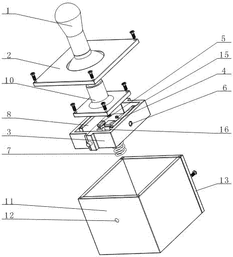
[0024] combined with Figure 1~2 The joystick based on inertial measurement includes a handle 1, an upper cover plate 2, an X-axis rotary block 3, a three-axis acceleration sensor 4, a radio frequency SOC5, a Y-axis rotary block 8, a base 11 and a circuit board 14, The middle part of the bottom surface of the base 11 is provided with a counterbore, and in the counterbore is provided with a reset device for the reset of the handle 1. The reset device is a return spring 7 or a rubber rod, wherein the preferred return spring 7, the reset The upper end of the device is fixed on the middle part of the lower bottom surface of the Y-axis turning block 8. In order to improve the stability of the reset device, a downwardly extending annular boss is provided in the middle part of the lower bottom surface of the Y-axis turning block...


PUM


Abstract

The invention discloses a control lever based on inertia measurement. An X-axis rotating block (3) and a Y-axis rotating block (8) are respectively arranged inside a base (11), and a handle can shake in any direction. A three-axis acceleration sensor (4) is arranged in the geometric center of the X-axis rotating block and the Y-axis rotating block, the postures of the handle (1) can be measured when the handle shakes, the displacement proportional digital signals of the handle on the two horizontal axes are obtained through calculation, and then the handle shaking can control the movement and postures of a controlled object. The control lever has the advantages of being simple in structure, high in gathering degree, small in size, high in control precision, free of abrasion in use and long in service life.

Description

【Technical field】 [0001] The invention relates to a joystick, in particular to a joystick based on inertial measurement. 【Background technique】 [0002] It is known that the joystick "also known as the control handle" is a common human-computer interaction interface, which can convert the rotation of the handle in different directions in three-dimensional space into two-dimensional proportional electrical signal output, so as to realize the control of the controlled object. Motion or attitude control, due to its good ergonomic characteristics, is widely used in remote radio control of heavy machinery, radar and navigation systems, robots, measurement systems, etc.; currently, joysticks can be divided into There are three types: potentiometer joysticks, photoelectric joysticks and Hall effect induction joysticks. Among them, the core device of potentiometer joysticks is the potentiometer, which is obtained by sliding the brush on the resistor body. The displacement is propor...

Claims


Application Information

Patent Timeline
Patent Type & Authority Applications(China)
IPC IPC(8): G06F3/0346
Inventor 王祥雒杨春蕾刘中华安洛生匡春临
Owner LUOYANG NORMAL UNIV
Why Eureka
Try Eureka