
Electronic expansion valve

An electronic expansion valve and valve body technology, applied in the field of control valves, can solve the problems of increasing the adjustment times of the expansion valve, reducing the curve adjustment accuracy, control waste, etc., and achieving the effects of reducing the adjustment times, reducing energy consumption, and improving stability

Active Publication Date: 2014-07-23
ZHEJIANG SANHUA INTELLIGENT CONTROLS CO LTD
View PDF5 Cites 18 Cited by
  • Summary
  • Abstract
  • Description
  • Claims
  • Application Information

AI Technical Summary

Problems solved by technology

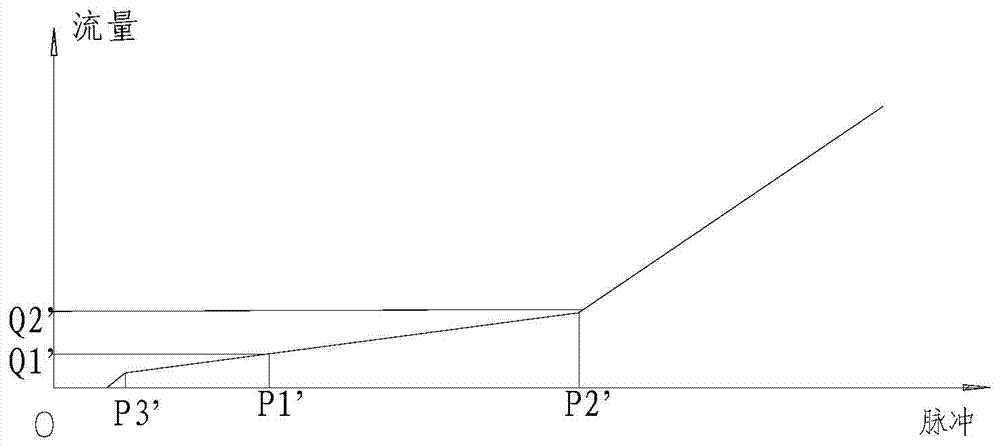
However, although the above technology can improve the accuracy of the electronic expansion valve at a small opening to a certain extent, due to the sudden change point in the entire flow curve and the influence of manufacturing errors, the position of P3' fluctuates greatly, generally 40 - The difference of 60 pulses will cause a difference of at least 40 pulses at P2' point, resulting in unpredictable flow before and after P2' point, thus reducing the adjustment accuracy of the whole curve
At the same time, although the flow change law before P2' is consistent with (Q2'-Q1') / (P2'-P1')=K, and K is approximately a constant value, it is still very difficult to know how to change the increase ratio of a pulse flow , which will increase the number of expansion valve adjustments, affect the stability of the air conditioning system, and also cause a decrease in the energy efficiency ratio
Host manufacturers will also rely too much on the accuracy of fixed-point flow control, resulting in a lot of unnecessary control waste

Method used


Image

  • Electronic expansion valve
  • Electronic expansion valve
  • Electronic expansion valve

Examples


Embodiment Construction

[0038] In order to enable those skilled in the art to better understand the technical solutions of the present invention, the present invention will be further described in detail below in conjunction with the accompanying drawings and specific embodiments.

[0039] Please refer to image 3 , image 3 A structure diagram of a typical electronic expansion valve given in the present invention.

[0040] The electronic expansion valve generally includes a coil 100 arranged on the outer periphery of the metal isolation cover 300 and a magnetic rotor 200 arranged on the inner periphery of the metal isolation cover 300. The coil 100 and the magnetic rotor 200 cooperate together and are equivalent to a stepping motor to constitute the driving part of the electronic expansion valve. .

[0041] The valve body 400 with the flow channel inlet 401 and the flow channel outlet 402 is airtightly welded with the isolation cover 300 to form an inner cavity 500 . The two connecting pipes 600 ...


PUM


Abstract

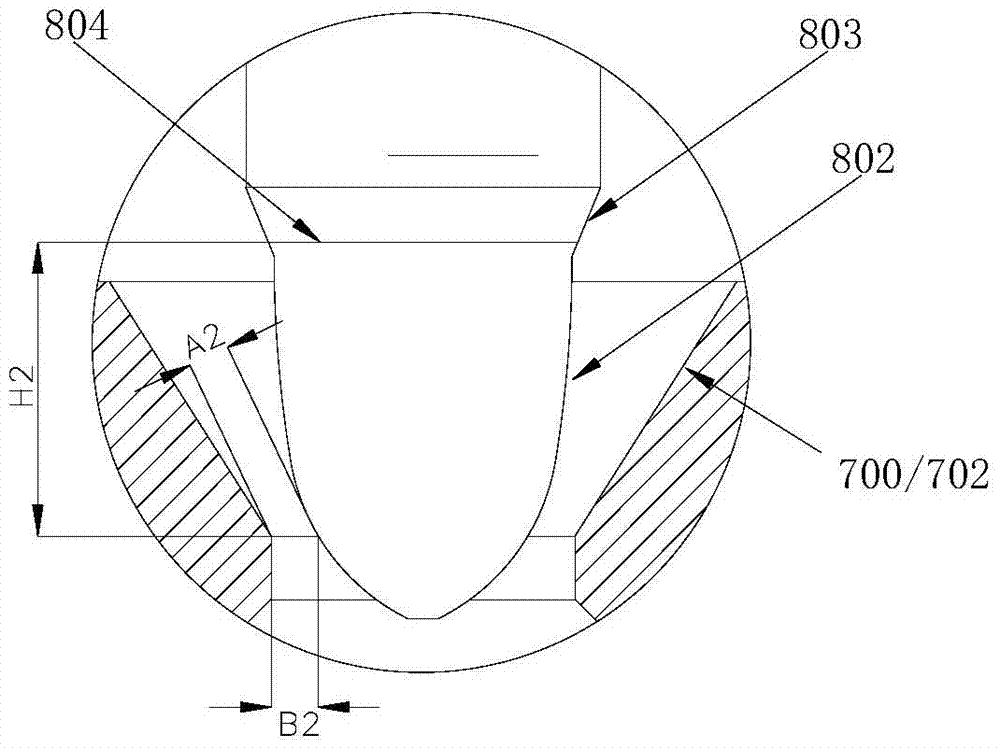
The invention relates to the technical field of control valves, and discloses an electronic expansion valve which comprises a drive part and a valve body part. The valve body part comprises a valve body with a flow path inlet and a flow path outlet, a valve core placed in an inner cavity of the valve body, and a valve core seat with a valve opening part. The electronic expansion valve is characterized in that the valve core comprises a body section and an adjusting section facing the valve core seat, the body section and the adjusting section are connected through a conical opening section, the adjusting section comprises at least one first circular arc section for adjusting a refrigerating fluid flow curve, the valve core seat comprises a valve opening part which is in a straight section and the conical opening section which is formed by extending from the valve opening part to the valve core, the diameter of the valve opening part is defined as phi 2, the diameter of the small end of a conical transitional section of the valve core is defined as phi 3, the diameter of the big end of the conical transitional section of the valve core is defined as phi 5, and the relation requirement of phi 3<phi 2<phi 5 is met. The electronic expansion valve facilitates adjustment of an air-conditioning system, reduces adjusting frequency, and improves the stability of the system.

Description

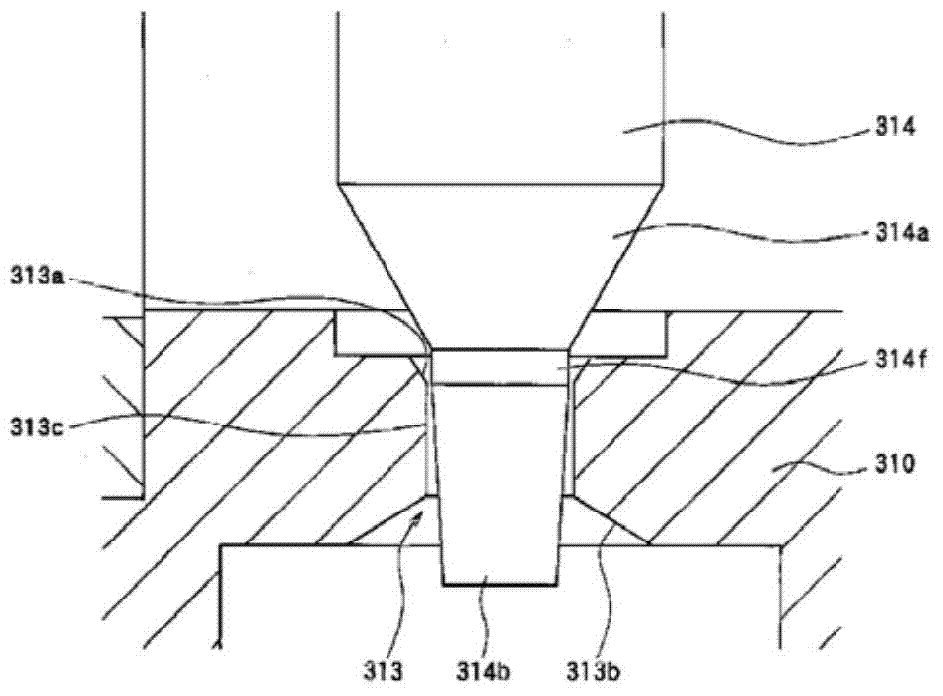
technical field [0001] The invention relates to the technical field of control valves, in particular to an electronic expansion valve for regulating refrigerant flow. Background technique [0002] In various refrigeration / heating equipment such as air conditioners, refrigerators, heat pump water heaters, etc., electronic expansion valves are usually used to regulate the flow of fluids. [0003] The electronic expansion valve usually includes two parts: a motor (driver part) with a stepping motor and a valve body part as an actuator part. The valve body part includes a valve body with a refrigerant flow path inlet and a flow path outlet. The spool in the inner cavity and the spool seat with the valve port part drive the axial movement of the spool relative to the valve port part by inputting pulse signals to the motor of the driving part to change the refrigerant flow through the valve port part. The flow rate is to adjust the refrigerant flow at the outlet of the flow path ...

Claims


Application Information

Patent Timeline
IPC IPC(8): F25B41/06F25B41/31
CPCF25B2500/01Y02B30/70F25B41/35
Inventor 不公告发明人
Owner ZHEJIANG SANHUA INTELLIGENT CONTROLS CO LTD
Learn More