
Torque self-checking inner curve hydraulic motor

A technology of hydraulic motor and inner curve, applied in the field of hydraulic motor and torque self-checking inner curve hydraulic motor, can solve the problems of inconvenient use, easy wear of collector rings and brushes, low accuracy, etc., to simplify the power transmission system. , The principle is simple and reliable, the maintenance is simple and convenient

Inactive Publication Date: 2014-07-23
赣州市双生电子有限公司
View PDF5 Cites 5 Cited by
  • Summary
  • Abstract
  • Description
  • Claims
  • Application Information

AI Technical Summary

Problems solved by technology

There are many types of torque sensors, which can be classified into two categories according to their working principles. The first type is based on shear stress, which uses strain gauges to measure the shear stress of the shaft to calculate the torque of the output shaft. The chip technology is closely related, and the accuracy is low. In addition, devices such as collector rings and brushes are required to output the signal, and the collector rings and brushes are easy to wear, resulting in low signal measurement accuracy.
The second type is based on torsional deformation. The torque of the output shaft is calculated by measuring the torsional deformation of the shaft by using the angle difference between the two ends of the torsion shaft. The commonly used methods are relative displacement method, photoelectric method and magnetic resistance method, etc., but the transmission shaft needs to be Disconnected, inconvenient to use
[0004] According to the existing torque measurement technology, whether it is based on shear stress or torsional deformation, the accuracy of the dynamic torque measurement of the output shaft is relatively low due to the difficult problems of temperature compensation and initial phase compensation.

Method used


Image

  • Torque self-checking inner curve hydraulic motor
  • Torque self-checking inner curve hydraulic motor
  • Torque self-checking inner curve hydraulic motor

Examples


Embodiment Construction

[0012] Embodiments of the present invention will be described in detail below in conjunction with the accompanying drawings.

[0013] It should be clear that the described embodiments are only some of the embodiments of the present invention, not all of them. Based on the embodiments of the present invention, all other embodiments obtained by persons of ordinary skill in the art without creative efforts fall within the protection scope of the present invention.

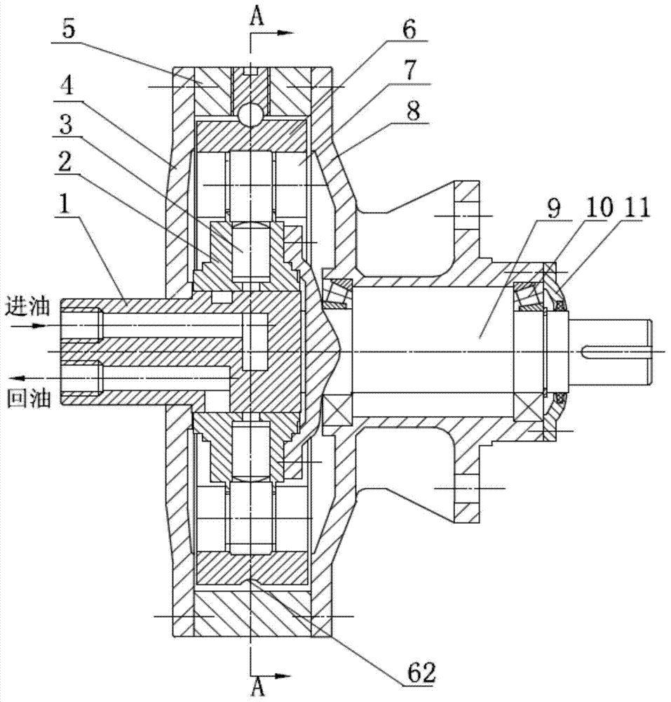
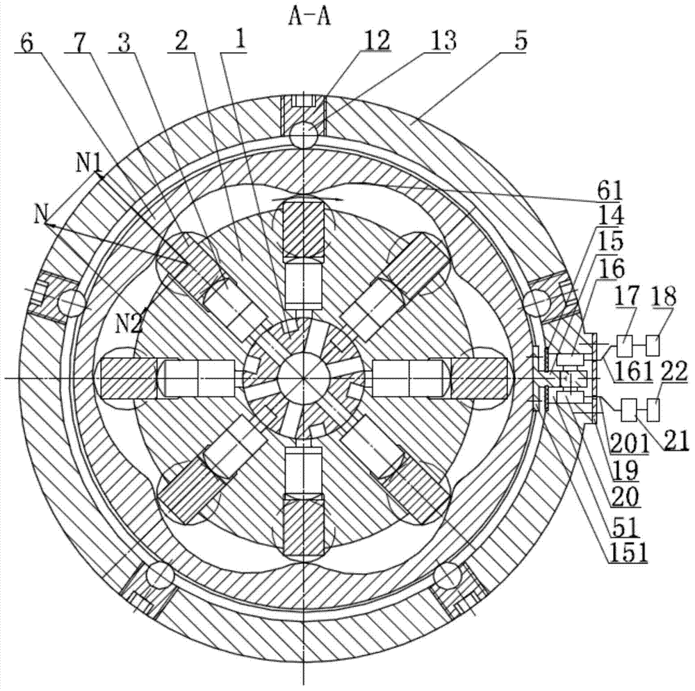
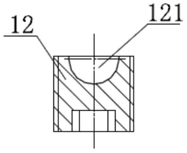
[0014] Such as figure 1 , figure 2 As shown, the torque self-inspection type internal curve hydraulic motor of the present invention includes a distribution shaft 1, an end cover 4, a housing 5, and a mounting frame 8. A cam ring 6 is installed in the housing 5, and the cam ring 6 and the housing 5 It can be rotated relatively. The rotor 2 is installed in the cam ring 6. Eight radial holes are evenly distributed in the rotor 2. There is a plunger 3 in each radial hole. The end of the plunger 3 has a roller set 7. T...


PUM


Abstract

The invention discloses a torque self-checking inner curve hydraulic motor, which comprises main parts such as a flow distribution shaft, a rotor, a plunger, a shell, a cam ring, a rolling wheel unit, an output shaft and the like, wherein the cam ring is supported in the shell through a steel ball; the cam ring and the shell can rotate relative to each other; a stopper is fixed at the outer side of the cam ring; a groove is correspondingly formed in the shell and the stopper extends into the groove; piezoelectric ceramic sensors are arranged above and below the stopper; and the torque of the output shaft is calculated through the stresses of the piezoelectric ceramic sensors. The inner curve hydraulic motor and a torque sensor are combined, so that a specialized torque sensor is saved, the power transmission system is simplified, the torque measuring principle is simple and reliable and the accuracy of dynamic torque measurement of the output shaft is greatly improved; the torque self-checking inner curve hydraulic motor can be widely applied to transmission systems of mining machinery, engineering machinery and crane transport machinery.

Description

technical field [0001] The invention relates to a hydraulic motor, in particular to a torque self-checking type internal curve hydraulic motor, which belongs to the field of hydraulic transmission. Background technique [0002] As we all know, the inner curve multi-action radial plunger hydraulic motor (referred to as the inner curve hydraulic motor) is a low-speed high-torque hydraulic motor, which is mainly composed of a stator, a rotor, a plunger, a roller set, a distribution shaft, an output shaft and an end cover. The inner wall of the stator is composed of multiple curved surfaces with the same shape. The stator is not only the housing of the motor, but also the surface of the guide rail of the rollers, which is used to support the roller group and complete the torque transmission. The inner curve hydraulic motor has a series of characteristics such as small size, light weight, large transmission torque, large speed range, high starting efficiency, and good low-speed s...

Claims


Application Information

Patent Timeline
IPC IPC(8): F03C1/247F03C1/32
Inventor 栾振辉李毅华朱立博
Owner 赣州市双生电子有限公司
Learn More