
Antenna, transmission device and switching mechanism

A technology of a switching mechanism and a transmission device, applied in the field of communication, can solve the problems of the influence of antenna reliability, the complex structure of the transmission system, and the high cost of the multi-frequency antenna transmission system

Pending Publication Date: 2020-03-24
COMBA TELECOM TECH (GUANGZHOU) CO LTD
View PDF0 Cites 3 Cited by
  • Summary
  • Abstract
  • Description
  • Claims
  • Application Information

AI Technical Summary

Problems solved by technology

[0004] However, the motors used to drive the phase shifter in the traditional transmission still correspond to the phase shifter transmission mechanism one by one, the number of motors has not been reduced, and the number of drive circuits in the control module has not been reduced as much as the number of motors
In this way, not only the cost of the control system and transmission system of the multi-frequency antenna is high, but also the structure of the transmission system is relatively complicated, and the reliability of the antenna is also affected

Method used


Image

  • Antenna, transmission device and switching mechanism
  • Antenna, transmission device and switching mechanism
  • Antenna, transmission device and switching mechanism

Examples


Embodiment Construction

[0027] In order to make the object, technical solution and advantages of the present invention clearer, the present invention will be further described in detail below in conjunction with the accompanying drawings and specific implementation methods. It should be understood that the specific embodiments described here are only used to explain the present invention, and do not limit the protection scope of the present invention.

[0028] It should be noted that when an element is referred to as being "fixed on", "disposed on", "fixed on" or "installed on" another element, it can be directly on the other element or there can also be an intervening element . When an element is referred to as being "connected to" another element, it can be directly connected to the other element or intervening elements may also be present. Furthermore, when one element is considered to be "transmission-connected" to another element, the two can be fixed in a detachable connection or in a non-deta...


PUM


Abstract

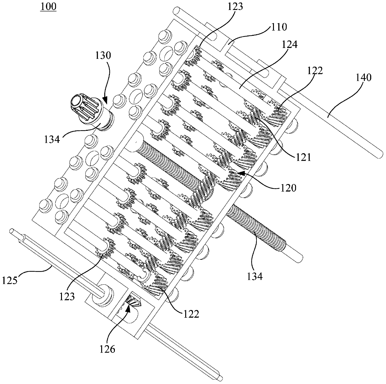
The invention discloses an antenna, a transmission device and a switching mechanism. The switching mechanism comprises a transmission part, the position selecting unit comprises a worm rotationally arranged on the transmission part, at least two worm wheels in transmission fit with the worm and driving gears in one-to-one correspondence with the worm wheels, a first transmission shaft is arrangedbetween each driving gear and the corresponding worm wheel, and every two adjacent driving gears are longitudinally or / and transversely staggered in the longitudinal direction and the transverse direction; and the driving unit is used for driving the transmission part to reciprocate along a preset track. The switching mechanism can selectively drive the output shaft to rotate, and can adapt to theincrease of the frequency band of the antenna without causing the complex transmission structure; according to the transmission device, the switching mechanism is adopted, power is provided for adjustment of at least two downward inclination angles, and a transmission system is simplified; the antenna adopts the transmission device, a transmission system is simplified, the antenna can adapt to the increase of the frequency band of the antenna, and the reliability of the working performance of the multi-frequency antenna is improved.

Description

technical field [0001] The invention relates to the technical field of communication, in particular to an antenna, a transmission device and a switching mechanism. Background technique [0002] With the increasing number of mobile communication terminal users, the demand for network capacity of sites in the mobile cellular network is increasing. At the same time, it is required to minimize the interference between different sites or even between different sectors of the same site, that is, to realize the network Maximize capacity and minimize interference. To achieve this purpose, it is usually achieved by adjusting the downtilt angle of the antenna beam on the station. [0003] Among the two methods of adjusting beam downtilt, mechanical downtilt and electronic downtilt, electronic downtilt has obvious advantages and is the current mainstream and future development trend. Electric downtilt control is mainly divided into two categories: built-in and external, and built-in ...

Claims


Application Information

Patent Timeline
IPC IPC(8): H01Q3/32
CPCH01Q3/32
Inventor 游建军黄潮生何海雁
Owner COMBA TELECOM TECH (GUANGZHOU) CO LTD
Learn More