Metering bottle
A bottom cap and liquid technology, applied in the field of metering bottles, can solve problems such as unpleasantness, liquid adhesion, and time-consuming metering
- Summary
- Abstract
- Description
- Claims
- Application Information
AI Technical Summary
Problems solved by technology
Method used
Image
Examples
Embodiment approach
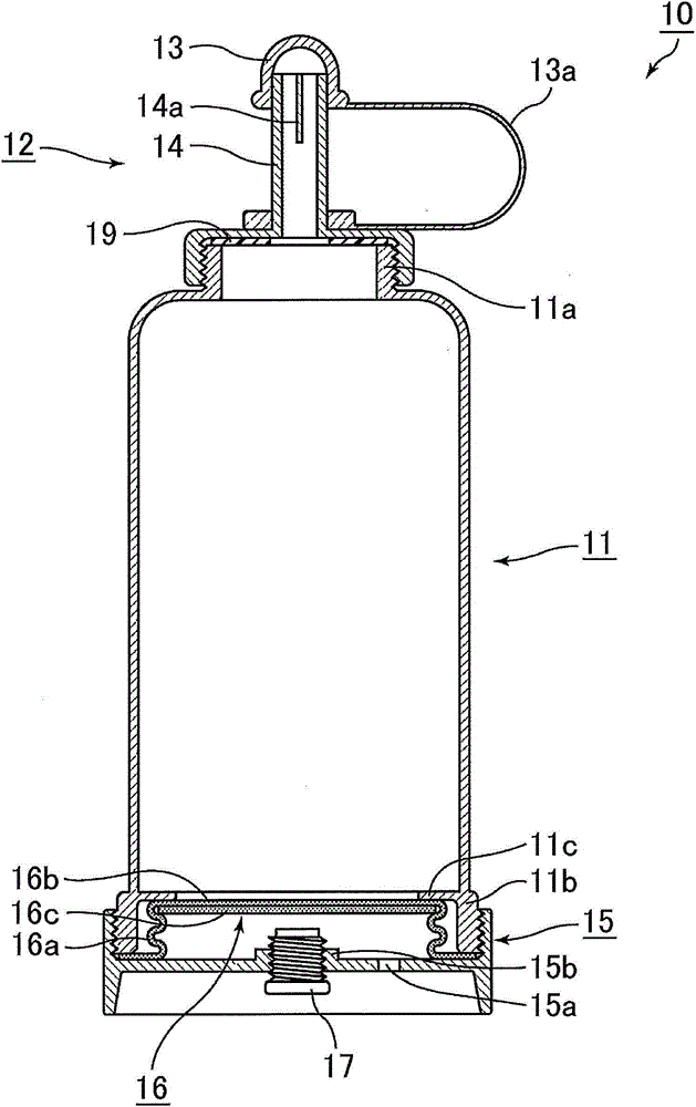
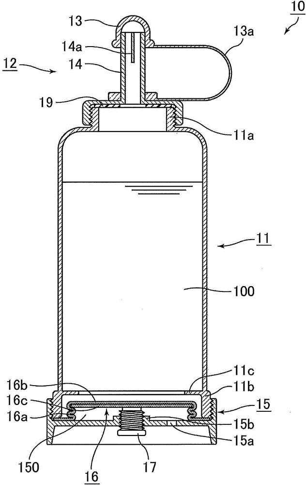
[0035] figure 1 It is a vertical cross-sectional view schematically showing an example of a metering bottle according to the first embodiment of the present invention, figure 2 is indicative of the figure 1 The metering bottle is shown in longitudinal section when it is filled with liquid.
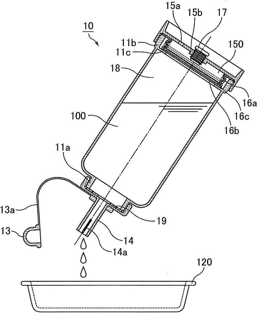
[0036] image 3 is a schematic representation of the use of figure 1 An explanatory diagram of the shown metering bottle pouring liquid into other containers.
[0037] Such as figure 1 As shown, the metering bottle 10 according to the first embodiment of the present invention is composed of a cylindrical metering bottle body 11 , an upper cap 12 provided on the upper part of the metering bottle body, and a bottom cap 15 provided on the lower part of the metering bottle body 11 .
[0038] The upper cover 12 is provided with a nozzle-shaped liquid pouring opening 14, and an auxiliary cover 13 connected to the upper cover 12 by a flexible rope 13a is arranged on the top end of the l...
no. 2 approach )
[0062] Next, a second embodiment which is one embodiment of the measuring bottle of the present invention will be described.
[0063] Figure 5 It is a vertical cross-sectional view schematically showing an example of a measuring bottle according to a second embodiment of the present invention.
[0064] Such as Figure 5 As shown, the mouth of the upper part of the measuring bottle body 21 constituting the measuring bottle 20 of the second embodiment is not as small as that of the first embodiment, but a screw thread is provided on the upper part of the cylindrical measuring bottle body 21. Mouth 21a.
[0065] In addition, a diaphragm 26 is formed at the bottom of the metering bottle body 21 by integral molding with the metering bottle body 21. The diaphragm 26 consists of a ring-shaped corrugated portion 26a arranged in the horizontal direction and a plate-shaped wall arranged in the center of the ring. Part 26b constitutes.
[0066] The upper cap 22 constituting the meas...
no. 3 approach )
[0071] Next, a third embodiment which is one embodiment of the measuring bottle of the present invention will be described.
[0072] Image 6 It is a vertical cross-sectional view schematically showing an example of a measuring bottle according to a third embodiment of the present invention.
[0073] Such as Image 6 As shown, the metering bottle body 31 constituting the metering bottle 30 of the third embodiment is substantially the same as the metering bottle body 11 of the metering bottle of the first embodiment. A threaded thread portion 31b is also provided.
[0074] Furthermore, the upper cap 12 is configured exactly the same as the upper cap 12 in the metering bottle 10 of the first embodiment.
[0075] On the other hand, the bottom cover 35 is different from the bottom cover in the first embodiment in that a cylindrical balloon-shaped member installation part 36 is provided at the central part 35b of the bottom cover 35, and a balloon-shaped member installation part...
PUM
 Abstract
Description
Claims
Application Information
 - R&D
- Intellectual Property
- Life Sciences
- Materials
- Tech Scout
- Unparalleled Data Quality
- Higher Quality Content
- 60% Fewer Hallucinations
Browse by: Latest US Patents, China's latest patents, Technical Efficacy Thesaurus, Application Domain, Technology Topic, Popular Technical Reports.
© 2025 PatSnap. All rights reserved.Legal|Privacy policy|Modern Slavery Act Transparency Statement|Sitemap|About US| Contact US: help@patsnap.com


