Mounting bracket for automobile rear bumper and rear collision beam

A technology for mounting brackets and rear collisions, applied in bumpers and other directions, can solve problems such as increased parts cost, poor strength, and unfavorable parts control, and achieve the effect of reducing maintenance costs, production costs, and facilitating rapid positioning

Active Publication Date: 2016-12-28
CHONGQING CHANGAN AUTOMOBILE CO LTD
View PDF6 Cites 0 Cited by
  • Summary
  • Abstract
  • Description
  • Claims
  • Application Information

AI Technical Summary

Problems solved by technology

Existing rear bumper mounting brackets such as Figure 4 As shown, the existing rear crash beam mounting bracket is as follows Figure 5 As shown, the two are independent brackets, which is not conducive to the control of parts, and will also increase the cost of parts to a certain extent
In addition, the existing rear bumper mounting bracket 7 has poor strength in the Z and X directions (that is, the vertical and horizontal directions), and the bumper is easy to move when the car is running, and even produces abnormal noises.
The existing rear collision beam mounting bracket 8 does not consider the force in the X direction during the design process. In the event of a collision, due to its poor strength, it is easy to cause serious deformation and increase maintenance costs.
The rear impact beam is installed on the rear impact beam mounting bracket with welded nuts. This installation method is not conducive to the rapid positioning of the rear impact beam and affects the installation efficiency of the staff.

Method used


Image

  • Mounting bracket for automobile rear bumper and rear collision beam
  • Mounting bracket for automobile rear bumper and rear collision beam
  • Mounting bracket for automobile rear bumper and rear collision beam

Examples


Embodiment Construction

[0012] In order to further explain the technical solution of the present invention, the present invention will be described in detail below in conjunction with the accompanying drawings.

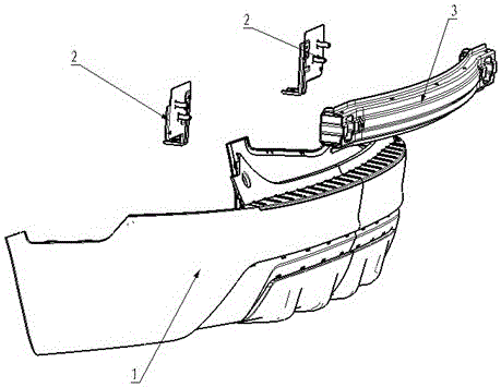
[0013] Such as figure 1 and figure 2 As shown, the mounting bracket 2 of the rear bumper of the automobile and the rear collision beam includes a vertical sheet metal part 22 and a horizontal sheet metal part 21, and the horizontal sheet metal part 21 is positioned at the lower end of the vertical sheet metal part 22, and is connected with the vertical sheet metal part 22. The straight sheet metal parts are connected as a whole, the horizontal sheet metal part 21 is provided with a bumper mounting nut 26, and the vertical sheet metal part 22 is welded with rear collision beam mounting bolts 25. The left and right sides and the lower end of the vertical sheet metal part 22 and the left and right sides of the horizontal sheet metal part 21 are provided with flanges 27, and the vertical shee...


PUM


Abstract

The invention discloses a mounting support of an automotive rear bumper and a rear collision beam. The mounting support comprises a vertical stamping part and a horizontal stamping part. The horizontal stamping part is arranged at the lower end of the vertical stamping part and integrated with the vertical stamping part. A bumper mounting nut is arranged on the horizontal stamping part, and a rear collision beam mounting bolt is welded on the vertical stamping part. The mounting support can be used for mounting the automotive rear bumper and the rear collision beam, the strength of the mounting support is improved, and mounting efficiency of the rear collision beam is improved.

Description

technical field [0001] The invention relates to parts of automobiles, and more specifically relates to a rear bumper and a mounting bracket for a rear collision beam of an automobile. Background technique [0002] With the continuous development of the automobile industry, the design requirements for the integration, installation reliability and cost of various mounting brackets for cars are getting higher and higher. Existing rear bumper mounting brackets such as Figure 4 As shown, the existing rear crash beam mounting bracket is as follows Figure 5 As shown, the two are mutually independent brackets, which is not conducive to the control of parts, and will also increase the cost of parts to a certain extent. In addition, the existing rear bumper mounting bracket 7 has poor strength in Z and X directions (that is, vertical and horizontal directions), and the bumper is easy to move when the car is running, and even produces abnormal noise. The existing rear collision bea...

Claims


Application Information

Patent Timeline
Patent Type & Authority Patents(China)
IPC IPC(8): B60R19/04
Inventor 廖水平曾俊王凯剑祝前广
Owner CHONGQING CHANGAN AUTOMOBILE CO LTD
Why Eureka
Try Eureka