
Anti-dust device, connector assembly and method for positioning optical fiber in straight-through type quick connector

A technology of connector assembly and dust-proof device, which is applied to the coupling of optical waveguides and other directions, can solve the problems of complex structure, easy damage to the built-in optical fiber of the optical fiber connector, and no positioning function, and achieves the effect of simple structure and easy removal.

Inactive Publication Date: 2014-07-16
TYCO ELECTRONICS (SHANGHAI) CO LTD
View PDF6 Cites 7 Cited by
  • Summary
  • Abstract
  • Description
  • Claims
  • Application Information

AI Technical Summary

Problems solved by technology

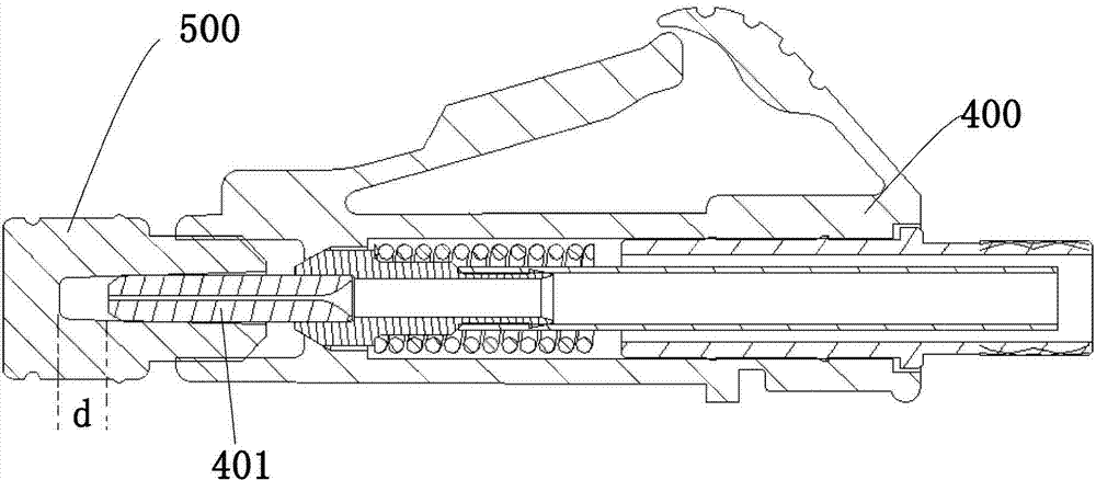
Because the gap d is too large, the optical fiber protruding from the ferrule 401 cannot touch the bottom of the dust cap 500, therefore, there is no positioning function for the optical fiber protruding from the ferrule 401
In addition, the existing dust cap has a relatively complicated structure, and when removing the dust cap 500, a relatively large force is required, and the built-in optical fiber in the optical fiber connector is easily damaged when the dust cap is removed.

Method used


Image

  • Anti-dust device, connector assembly and method for positioning optical fiber in straight-through type quick connector
  • Anti-dust device, connector assembly and method for positioning optical fiber in straight-through type quick connector
  • Anti-dust device, connector assembly and method for positioning optical fiber in straight-through type quick connector

Examples


Embodiment Construction

[0037] While the present invention will be fully described with reference to the accompanying drawings containing preferred embodiments of the invention, it should be understood before proceeding that those skilled in the art may modify the invention described herein while obtaining the technical effects of the present invention. Therefore, it should be understood that the above description is a broad disclosure for those skilled in the art, and its content is not intended to limit the described exemplary embodiments of the present invention.

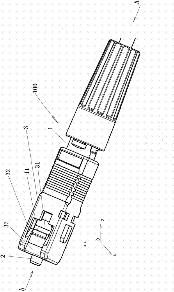
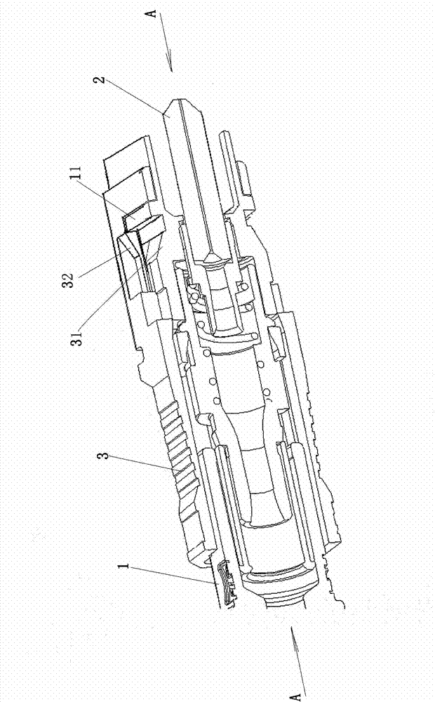
[0038] figure 2 is a schematic perspective view showing an optical fiber connector 100 according to an exemplary embodiment of the present invention; image 3 is showing figure 2 An enlarged partial cross-sectional view of fiber optic connector 100 along axis A-A is shown. The optical fiber connector 100 of the present invention can be, for example, a straight-through type optical fiber connector for fast connection, and can be combin...


PUM


Abstract

The invention provides an anti-dust device, a connector assembly and a method for positioning an optical fiber in a straight-through type quick connector. The anti-dust device comprises a base portion, two cantilevers approximately and parallelly extending from two opposite ends of the base portion and used for enabling the anti-dust device on an optical fiber connector, a sleeve extending from the base portion between the cantilevers and used for accommodating a plug core of the optical fiber connector when the anti-dust device is installed on the optical fiber connector. The sleeve comprises a positioning face formed at the bottom of the sleeve, wherein a certain distance is reserved between the positioning face and the end of the optical fiber plug core to enable the end face of the optical fiber extending out of the plug core to be rightly in contact with the positioning face so as to achieve optical fiber positioning when the anti-dust device is installed on the optical fiber connector. The sleeve of the anti-dust device can accurately position the optical fiber extending out of the plug core of the optical fiber connector.

Description

technical field [0001] The present invention relates to an optical fiber connector used in data communication and telecommunication applications, in particular to a dust-proof device for an optical fiber connector, a connector assembly including the dust-proof device, and a direct-through quick connection The method of positioning the optical fiber in the device. Background technique [0002] In various network communication terminals such as computers, routers, servers, switches, etc., the user terminal is usually electrically connected to an external cable by inserting a plug connector into, for example, a socket connector fixed on a wall. In particular, in optical fiber communication, it is necessary to use optical fiber connectors to realize connection, distribution, switching, etc. between different optical fibers. [0003] figure 1 It is a three-dimensional schematic diagram showing a conventional optical fiber connector 400 and a dustproof cap 500 installed on the o...

Claims


Application Information

Patent Timeline
Patent Type & Authority Applications(China)
IPC IPC(8): G02B6/38G02B6/36
Inventor 陈玲玲范文勇
Owner TYCO ELECTRONICS (SHANGHAI) CO LTD
Learn More