
Multi-section reaming cast-in-place pile construction method

A construction method and cast-in-situ pile technology, which is applied to sheet pile walls, foundation structure engineering, construction, etc., can solve problems such as low construction efficiency, construction progress constraints, and complex hole-forming construction technology of extruded and expanded piles, so as to improve construction efficiency, The effect of ensuring the quality of piles

Active Publication Date: 2014-07-16
BEIJING RONGCHUANG GEOTECHNICAL ENG CO LTD
View PDF8 Cites 24 Cited by
  • Summary
  • Abstract
  • Description
  • Claims
  • Application Information

AI Technical Summary

Problems solved by technology

[0010]a. The hole-forming process of extruded and expanded piles is complex, requiring a variety of mechanical equipment to be constructed alternately. The extruded and expanded equipment occupies a large construction site, and low construction efficiency has become a prominent problem
b. The construction process of pile formation is complicated, the drilling wall encounters a variety of mechanical lifting and scraping, and the hole drying time is long, so it is difficult to control the quality of the hole formation
c. The bearing plate is not formed by extrusion and expansion at one time. The extrusion arm is greatly affected by the characteristics of the formation and manual operation factors, and the direction of expansion is easily shifted. The wedge-shaped cavity formed by each extrusion of the working arm may not be mutually They are overlapped to form a complete set-up cavity, but the outer edge of the cavity and the vertical misalignment of the cavity are unavoidable, and the molding size of the cavity cannot be guaranteed
d. In view of the operating characteristics of the extrusion equipment and the characteristics of the soil layer, during the extrusion process, the apertures at the upper and lower ends of the disk are reduced, the diameter of the disk is reduced, and the height of the outer edge of the disk is reduced, which seriously affects the bearing capacity of the single pile.
e. The extrusion and expansion construction technology itself has little adaptability to the stratum. In the sandy soil layer, the extrusion and expansion support plate is easy to collapse the hole, and it cannot be squeezed in the hard stratum, so the plate position design has to be changed.
f. In the process of extrusion and expansion, a large amount of sediment will fall into the pan cavity or the bottom of the hole. There is no way to clean up the sediment in the pan cavity, and we can only let it go, which greatly reduces the bearing capacity of the pan; The sediment needs to be mobilized to drill back and forth for the first hole cleaning, which is labor-intensive and time-consuming
[0011] In summary, It can be seen that the construction of variable-diameter cast-in-place piles in the prior art requires a variety of construction machines and equipment to be constructed alternately, that is, the three processes of drilling, reaming and hole cleaning need to be completed by replacing different construction equipment; The construction process has become complicated, equipment scheduling and quality monitoring are difficult, and the construction progress is severely restricted; the forming effect of the bearing plate (enlarging head) is difficult to achieve the expected goal, the sediment at the bottom of the plate is difficult to remove, and the quality of hole formation and pile formation is not stable enough; Due to the defects of construction equipment and construction technology, the technical and economic advantages of the above-mentioned pile types are not outstanding, which restricts its application scope

Method used

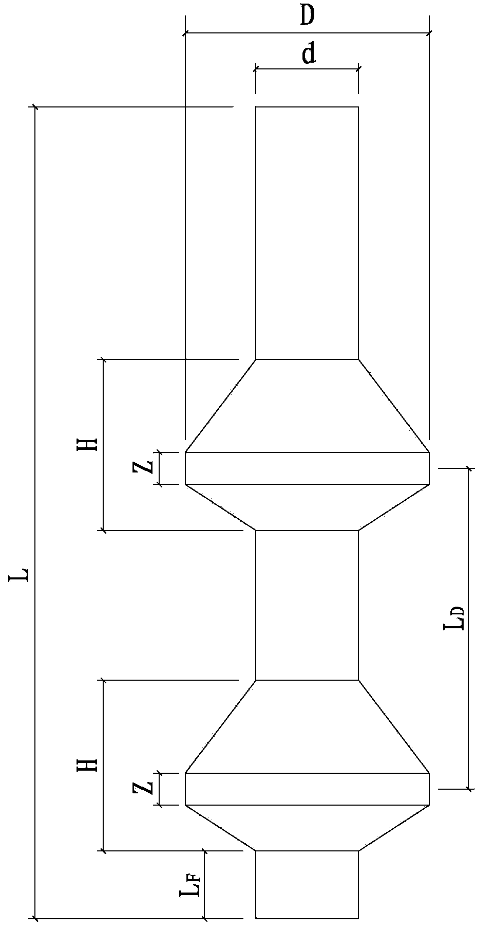

Image

  • Multi-section reaming cast-in-place pile construction method
  • Multi-section reaming cast-in-place pile construction method
  • Multi-section reaming cast-in-place pile construction method

Examples


Embodiment Construction

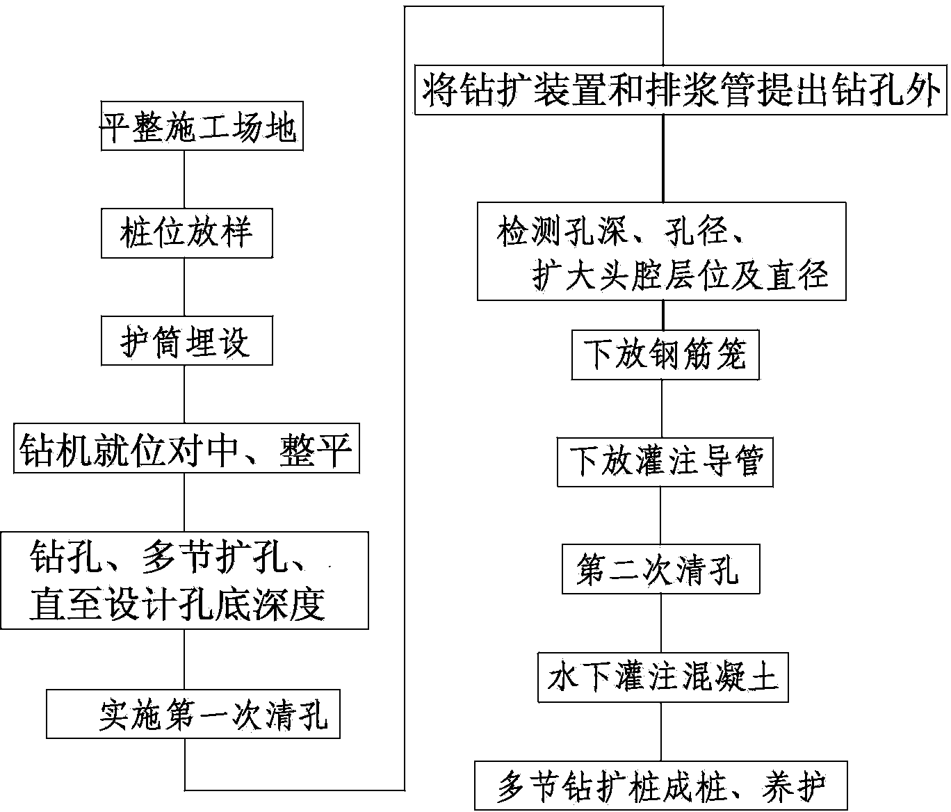
[0035] The construction method of multi-section drilled and expanded cast-in-situ piles according to the present invention is characterized in that it comprises the following operation steps:

[0036] ① Leveling the construction site, setting out pile positions and laying casings in sequence;

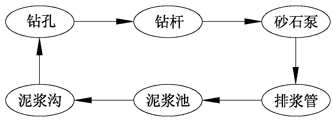
[0037] ②Centering and leveling the drilling rig in place: Move the drilling rig to the pile position, align the drill bit tip of the drilling rig expansion device with the center point of the pile position in the casing and level the frame so that the drill bit can be aligned on the pile position. Drilling holes are opened in the center; after the drilling rig is centered and leveled, the frame legs of the drilling rig or other contact parts with the ground should be stabilized and compacted to prevent the equipment from tilting or misaligning during the drilling construction process; A mud pool and a mud ditch are dug on one side;

[0038] ③ Drilling, multi-section reamin...


PUM


Abstract

The invention discloses a multi-section reaming cast-in-place pile construction method which includes the following work steps that (1) construction field leveling, pile lofting and pile casing embedding are sequentially carried out; (2) a drilling rig takes the place and carries out centering and leveling; (3) drilling and multi-section reaming are carried out until a designed hole bottom depth is achieved; (4) primary hole cleaning is carried out; (5) a reaming device and a discharge tube are pulled out of a drilled hole; (6) a reinforcement cage is laid down; (7) a cast-in-place guide tube is laid down; (8) secondary hole cleaning is carried out through a cast-in-place guide tube; (9) concrete is poured underground; (10) pile-forming and maintenance of a multi-section reaming cast-in-place pile are carried out. By means of the method, multi-section reaming cast-in-place pile construction is achieved through one machine at a time, the problems that in the prior art, multiple machines construct the pile alternatively, construction efficiency is low and construction quality is difficult to guarantee are solved, and the variable-diameter cast-in-place pile construction technology is pushed to a new height. The construction method can guarantee pile forming quality, can greatly improve construction efficiency, and lays solid foundations for popularization and application of the multi-section reaming cast-in-place pile.

Description

technical field [0001] The invention relates to a variable-diameter cast-in-situ pile construction technology, in particular to a construction method for multi-section drilled and expanded cast-in-situ piles. Background technique [0002] Bored cast-in-place piles with mud retaining walls first appeared abroad and have a history of more than 100 years. They are also one of the earliest and most widely used pile types in my country. On the basis of mud retaining bored piles, variable-diameter cast-in-place piles are produced, such as bored bottom-expanded cast-in-place piles, rotary expansion piles, and squeezed-expanded cast-in-place piles. The multi-section drilled and expanded cast-in-place pile disclosed by the present invention also belongs to the category of variable-diameter cast-in-place piles. This type of pile utilizes the principle that the end resistance of the same area is far greater than the side friction resistance, and several enlarged heads (expanded heads) ...

Claims


Application Information

Patent Timeline
Patent Type & Authority Applications(China)
IPC IPC(8): E02D5/38E02D5/48
Inventor 沈保汉张宝成齐迎春
Owner BEIJING RONGCHUANG GEOTECHNICAL ENG CO LTD
Learn More