


Quick Research
Generate reliable direction feasibility study reports for your R&D in just a few steps.

Technical Q&A
Discover and master advanced knowledge NOW. Basics, ideas, possibilities, all at once.

Find Solutions
As an expert in R&D theories, this can generate solutions to your technical problems instantly.

Evaluate Feasibility
Analyze your overall solution with one click, know your potential R&D risks in advance.

Monitor Landscape
Get weekly tech updates, stay abreast of the latest tech innovations and key insights.
Occupancy driven patient room environmental control
An environment and occupant technology, applied in the field of ward environment control, can solve problems such as low efficiency and unacceptable hospital reception, and achieve the effect of optimizing energy efficiency performance
- Summary
- Abstract
- Description
- Claims
- Application Information
AI Technical Summary
Problems solved by technology
Method used
Image

Examples
Embodiment Construction
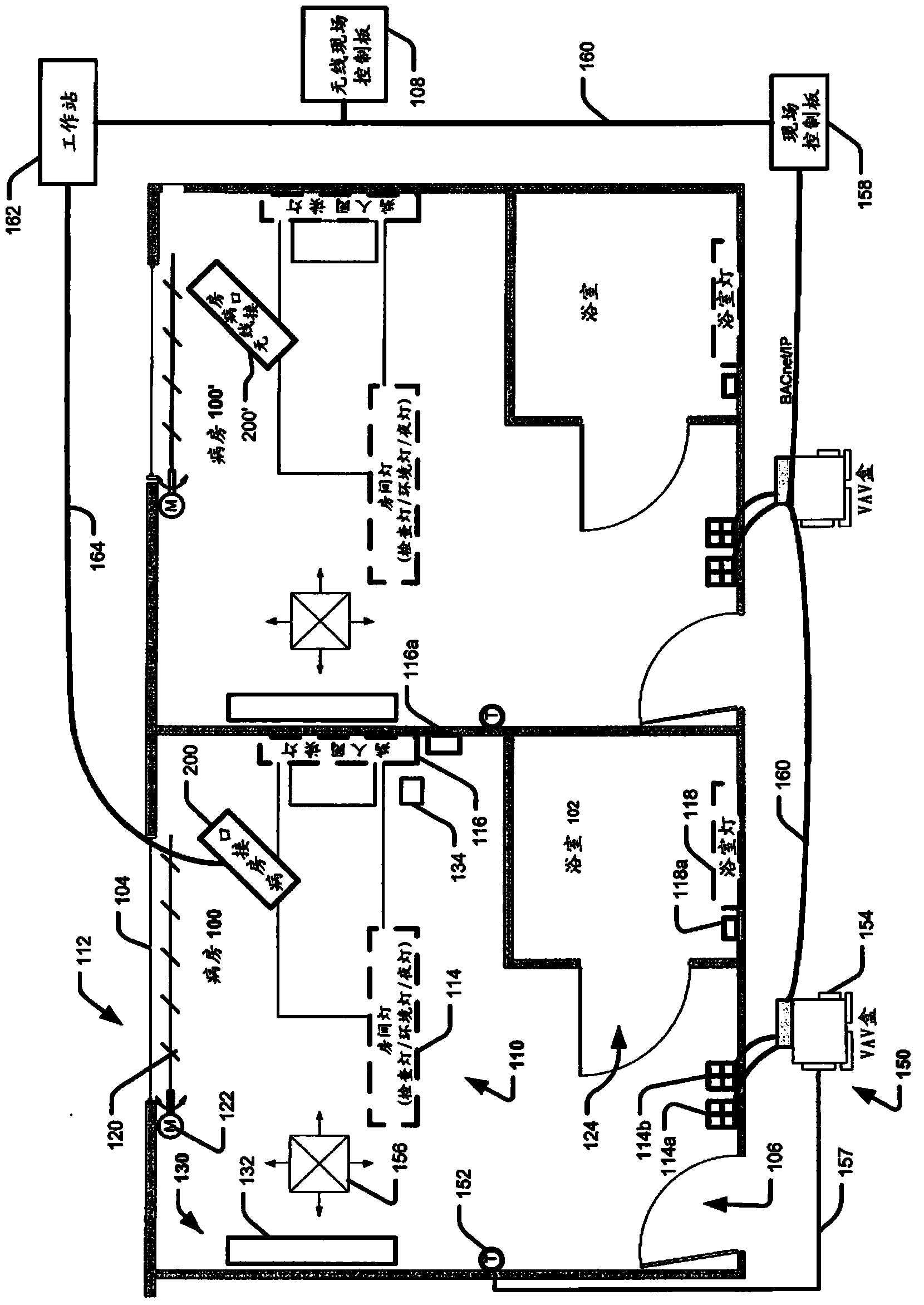
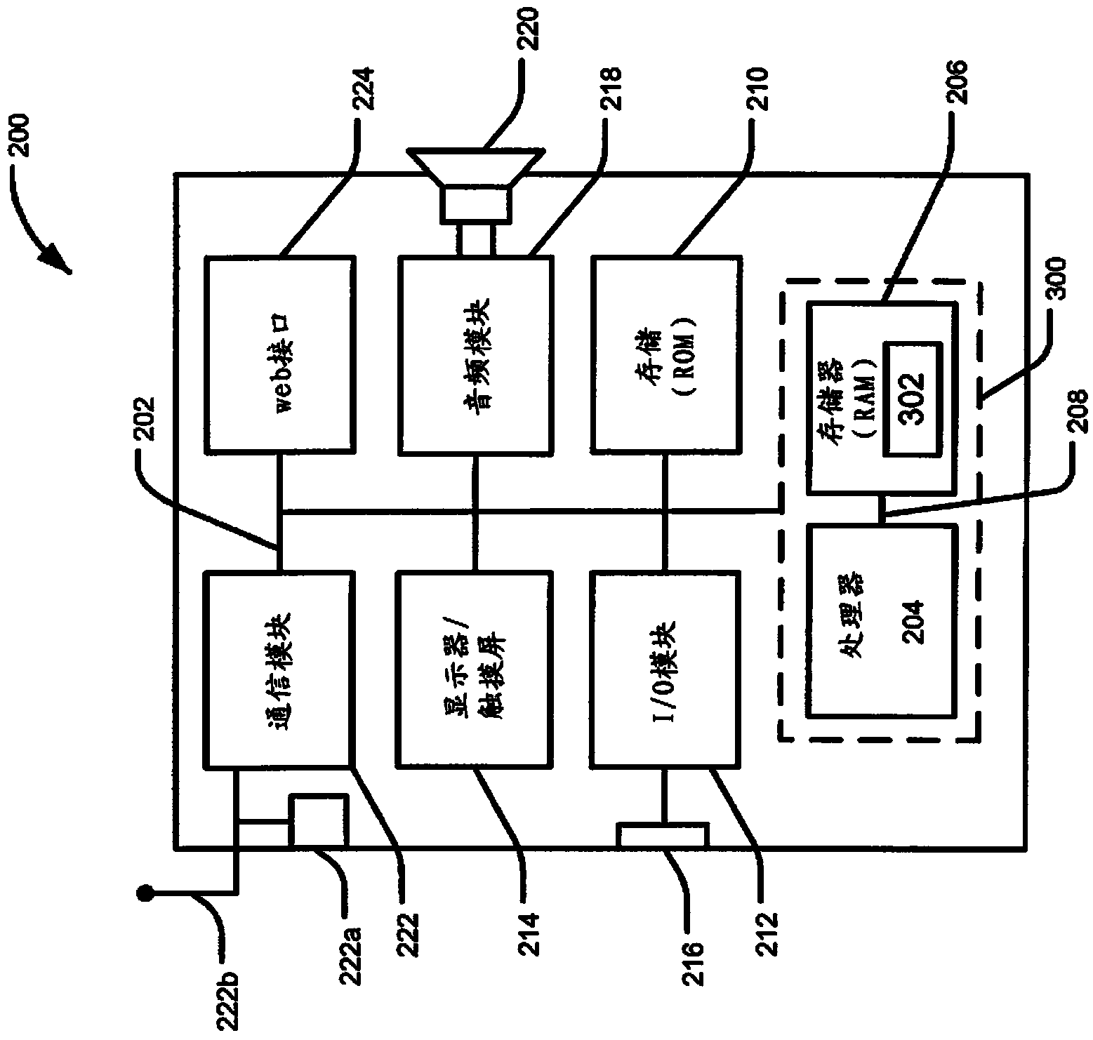
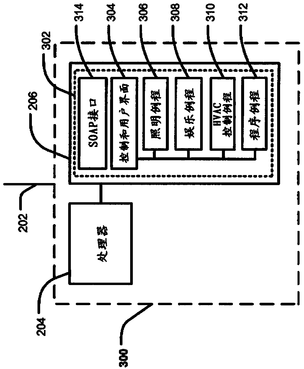
[0023] Provides a comprehensive solution for local environmental control in healthcare facilities. Occupancy drives the ward environmental control system. This comprehensive solution for patient rooms and other healthcare facility rooms includes building management systems such as heating, ventilation, and air conditioning (HVAC) automated building control systems (eg; APOGEE Insight from Siemens Building Technologies). Other building automation control systems and / or HVAC units may be used. This comprehensive solution can also include real-time positioning systems, such as the Ekahau system from Siemens. Other positioning systems may be used. The comprehensive solution may include a SOAP interface for managing communication between components. Other communications may be used.
[0024] The integrated solution provides a patient room environment (ie ventilation, temperature, light, windows and shades) to be adjusted based on patient occupancy (eg patient's real-time locati...
PUM
 Abstract
Description
Claims
Application Information
 - R&D Engineer
- R&D Manager
- IP Professional
- Industry Leading Data Capabilities
- Powerful AI technology
- Patent DNA Extraction
Browse by: Latest US Patents, China's latest patents, Technical Efficacy Thesaurus, Application Domain, Technology Topic, Popular Technical Reports.
© 2024 PatSnap. All rights reserved.Legal|Privacy policy|Modern Slavery Act Transparency Statement|Sitemap|About US| Contact US: help@patsnap.com