
Internal gear oil pump for vehicles

一种内啮合、齿轮式的技术,应用在旋转活塞式泵、泵、旋转活塞式/摆动活塞式的泵部件等方向,能够解决从动齿轮旋转中心偏转、从动齿轮旋转阻力增大、动压平衡不充分等问题,达到效率高的效果

Inactive Publication Date: 2016-01-06
TOYOTA JIDOSHA KK
View PDF13 Cites 0 Cited by
  • Summary
  • Abstract
  • Description
  • Claims
  • Application Information

AI Technical Summary

Problems solved by technology

[0004] However, in the internal gear oil pump for vehicles as described above, for example, when rotating at a low speed and / or when high oil pressure is generated, there is a gap between the outer peripheral surface of the driven gear and the inner peripheral surface of the pump chamber. The balance of the dynamic pressure generated between them is not sufficient, and there is a problem that the driven gear is unstable or the rotation center of the driven gear is deflected (vibration れる).
The deflection of the center of rotation of the driven gear causes the lubrication state between the outer peripheral surface of the driven gear and the inner peripheral surface of the pump chamber to become a boundary lubrication state, resulting in friction loss and increased rotational resistance of the driven gear. Big

Method used


Image

  • Internal gear oil pump for vehicles
  • Internal gear oil pump for vehicles
  • Internal gear oil pump for vehicles

Examples


Embodiment 1

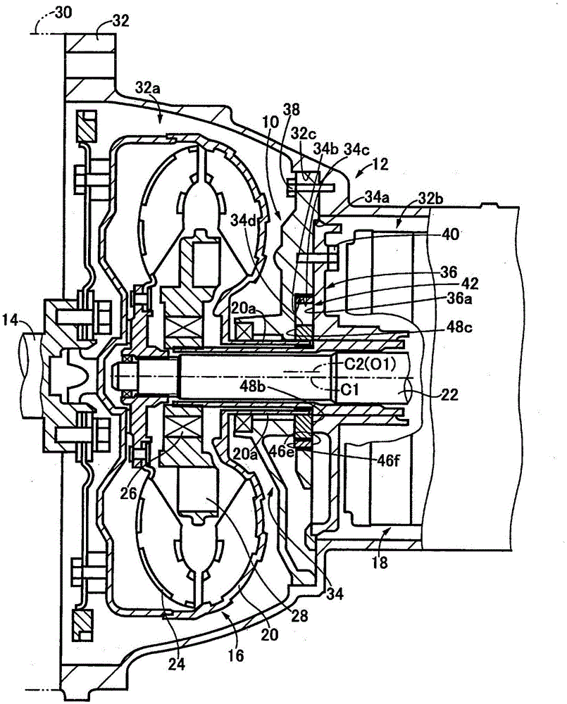
[0048] figure 1 It is a partial cross-sectional view showing a part of a vehicle power transmission device 12 including a vehicle internal gear type oil pump (hereinafter, referred to as an oil pump) 10 according to an embodiment of the present invention. The power transmission device 12 for a vehicle includes a torque converter 16 and a stepped automatic transmission 18 provided at a rear stage of a crankshaft 14 of an engine that is a drive source of the vehicle.

[0049] in figure 1 Among them, the torque converter 16 includes: a pump impeller 20 which is connected to the crankshaft 14 so as to be capable of transmitting power; and a turbine impeller 24 which is provided to be able to rotate relative to the pump impeller 20 and is connected to the automatic transmission 18 so as to be capable of transmitting power. The input shaft 22; and the stator impeller 28, which are arranged between the pump impeller 20 and the turbine impeller 24, and are rotatably supported via the one-...

Embodiment 2

[0104] Next, other embodiments of the present invention will be described. In addition, in the following description, the same reference numerals are attached to the parts common to the embodiments, and the description is omitted.

[0105] Compared with the oil pump 10 of the first embodiment, the oil pump of this embodiment is different only in that the shape of the first dynamic pressure generating groove 46i is different from that of the first dynamic pressure generating groove 46c of the first embodiment, and the other configuration is substantially the same. .

[0106] Such as Figure 18 As shown, the radial depth D1 of the driven gear 46 of the first dynamic pressure generating groove 46i is set so as to extend from the deepest part of the first dynamic pressure generating groove 46i to the inside of the pump body 34, as in the first embodiment. The ratio of the distance h1 of the gap H1 of the circumferential surface 34c to the distance h2 of the gap H2 from the outer circu...

Embodiment 3

[0109] Compared with the oil pump 10 of the first embodiment, the oil pump of this embodiment is different only in that the shape of the first dynamic pressure generating groove 46k is different from the first dynamic pressure generating groove 46c of the first embodiment, and the other configuration is substantially the same. .

[0110] Such as Figure 19 As shown, the radial depth D1 of the driven gear 46 of the first dynamic pressure generating groove 46k is set so as to extend from the deepest part of the first dynamic pressure generating groove 46k to the inside of the pump body 34, as in the first embodiment. The ratio of the distance h1 of the gap H1 of the circumferential surface 34c to the distance h2 of the gap H2 from the outer circumferential surface 46b of the driven gear 46 to the inner circumferential surface 34c of the pump body 34, that is, the gap ratio m1 (=h1 / h2) is predetermined In the range.

[0111] Such as Figure 19 As shown, the outer peripheral surface 4...


PUM


Abstract

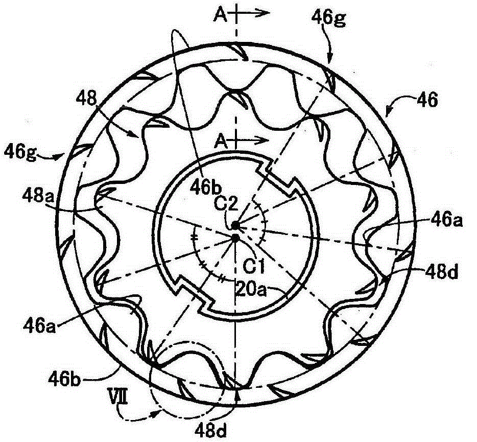
To provide a vehicle internal gear oil pump including a driven gear capable of obtaining a self-aligning effect of the driven gear while suppressing an increase in fluid friction acting on the driven gear. A concave first dynamic pressure generating groove (46c) is provided on the outer peripheral surface (46b) of the driven gear (46), and the depth D1 is set so that the pump The ratio of the gap H1 of the inner peripheral surface (34c) of the body (34) to the gap H2 from the outer peripheral surface (46b) of the driven gear (46) to the inner peripheral surface (34c), that is, the gap ratio m1, is within a predetermined range The predetermined range includes the maximum value of the dynamic pressure P1 generated by the first dynamic pressure generating groove (46c) and the minimum value of the fluid friction coefficient μ1 acting on the basis of the first dynamic pressure generating groove (46c). value. Therefore, the fluid friction coefficient μ1 acting on the driven gear (46) becomes the minimum and the dynamic pressure P1 generated in the first dynamic pressure generating groove (46c) becomes the maximum, and the fluid friction acting on the driven gear (46) can be suppressed. increase, while obtaining the self-aligning effect of the driven gear (46).

Description

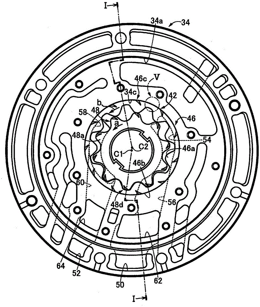
Technical field [0001] The present invention relates to a vehicle internal gear type oil pump equipped with a driven gear, and more particularly to a technique for optimizing the depth of a plurality of grooves recessed in the outer peripheral surface of the driven gear. Background technique [0002] The internal gear oil pump for a vehicle is equipped with: (a) a pump chamber, which is formed by a pump body and a pump cover; (b) an annular driven gear, which has internal teeth and faces the inner peripheral surface forming the pump chamber And (c) a drive gear having external teeth meshing with the internal teeth of the driven gear and arranged to be able to circulate around the driven gear The rotation center of the eccentric rotation center rotates and drives the driven gear to rotate. For example, Patent Documents 1 and 2 are like this. [0003] Generally, in the above-mentioned internal gear type oil pump for a vehicle, when the rotation of the driven gear is stopped, the dr...

Claims


Application Information

Patent Timeline
Patent Type & Authority Patents(China)
IPC IPC(8): F04C15/00F04C2/10
CPCF04C2/084F04C2/102F04C15/0042F04C2240/54F04C2240/56F04C18/08
Inventor 本田裕康
Owner TOYOTA JIDOSHA KK
Learn More