
Impulse type linear constant current drive LED circuit

A technology of linear constant current drive and linear constant current circuit, which is applied in the direction of electric lamp circuit layout, electric light source, lighting device, etc., can solve the problems of many peripheral devices, low power supply efficiency, complicated circuit, etc., and solve the problems of high power supply temperature, The effect of high current control precision and simple wiring

Active Publication Date: 2014-07-09
吴光敏
View PDF3 Cites 1 Cited by
  • Summary
  • Abstract
  • Description
  • Claims
  • Application Information

AI Technical Summary

Problems solved by technology

[0005] The present invention solves the problems of many peripheral devices, complicated circuits, low power supply efficiency and high temperature in the existing LED power supply, thereby providing a technical scheme for driving the LED circuit with a pulsed linear constant current

Method used


Image

  • Impulse type linear constant current drive LED circuit
  • Impulse type linear constant current drive LED circuit

Examples


Embodiment Construction

[0033] The present invention will be further described below in conjunction with the accompanying drawings and specific embodiments, but not as a limitation of the present invention.

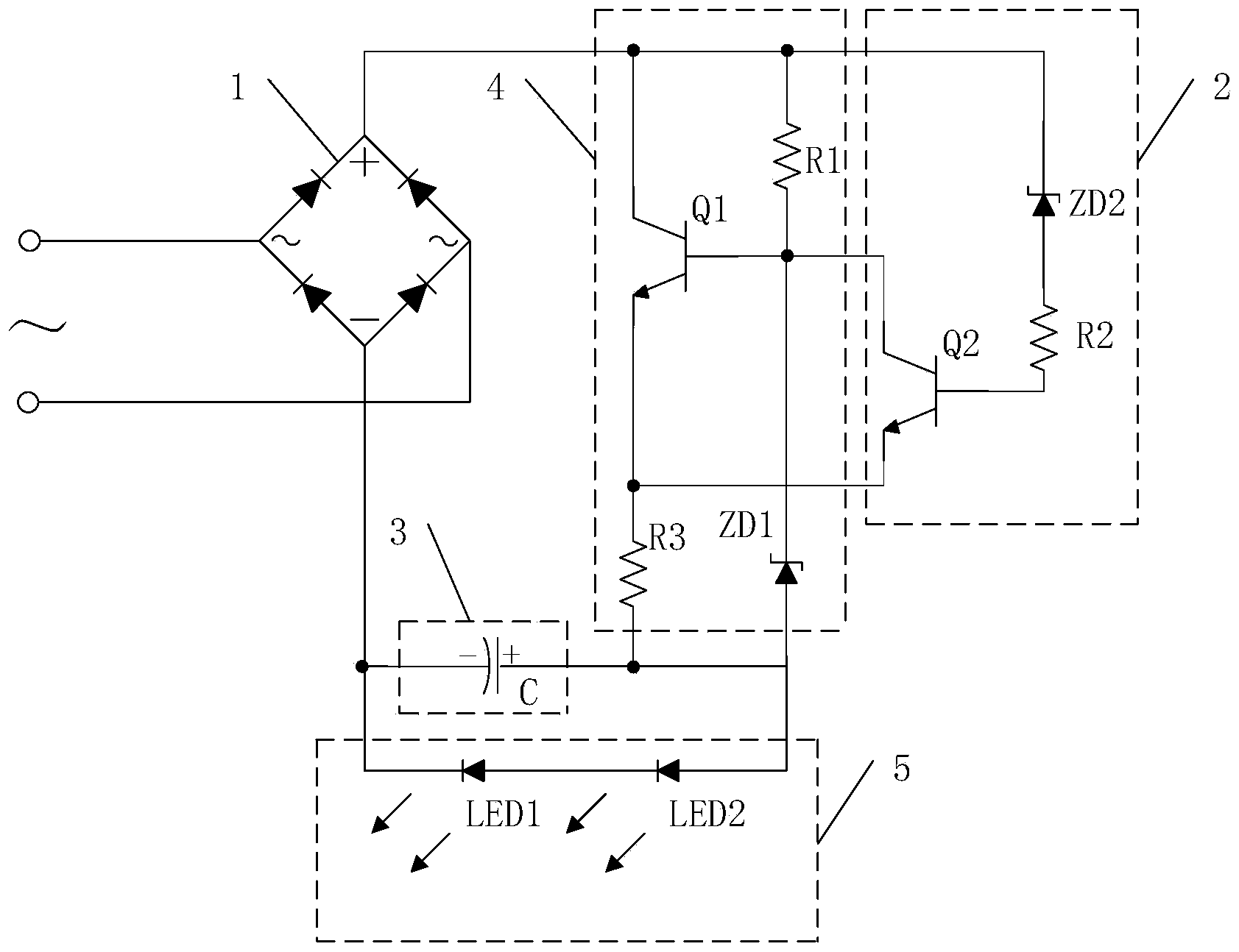
[0034] Such as figure 1 As shown, the present invention provides a pulse type linear constant current drive LED circuit, comprising: rectifier bridge stack circuit 1, linear constant current circuit 4, LED circuit 5 and pulse control circuit 2;

[0035] The bridge rectifier circuit 1 forms a half-wave sine wave signal under the control of an AC voltage;

[0036] The linear constant current circuit 4 is connected between a positive pole and a negative pole of the bridge rectifier circuit 1, and is used to output a constant current according to a half-wave sine wave signal;

[0037] The LED circuit 5 is connected between an output terminal of the linear constant current circuit 4 and the negative pole of the rectifier bridge stack circuit 1;

[0038] The pulse control circuit 2 is connected to t...


PUM


Abstract

The invention discloses an impulse type linear constant current drive LED circuit and relates to the technical field of LEDs. A half-wave sine wave signal is formed by a bridge rectifier circuit under the control of an alternating-current voltage; a linear constant-current circuit is connected between a positive electrode of the bridge rectifier circuit and a negative electrode of the bridge rectifier circuit and used for outputting constant current according to the half-wave sine wave signal; an LED circuit is connected between an output end of the linear constant-current circuit and the negative electrode of the bridge rectifier circuit; an impulse control circuit is connected with the bridge rectifier circuit and the linear constant-current circuit and used for forming an impulse voltage signal according to the half-wave sine wave signal and outputting the impulse voltage signal to the LED circuit. The LED circuit will be opened when alternating-current sine voltage increases to be higher than the forwarding voltage of the LED circuit and will be closed when the alternating-current sine voltage drops to be approximate to the forwarding voltage of the LED circuit, loss of the part by which sine voltage is higher than the forwarding voltage of the LED circuit is avoided, efficiency of the linear constant-current circuit is improved, the temperature of a power supply is prevented from being too high, and the impulse type linear constant current drive LED circuit has the advantages that the number of devices is small and the circuit is simple.

Description

technical field [0001] The invention relates to the technical field of LEDs, in particular to a linear constant current driving LED circuit. Background technique [0002] LED light is a kind of semiconductor diode, which can convert electrical energy into light energy. Like ordinary diodes, light-emitting diodes are composed of a PN junction and also have unidirectional conductivity. When a forward voltage is applied to the light-emitting diode, the holes injected from the P region to the N region and the electrons injected from the N region to the P region are respectively connected to the electrons in the N region and the vacancies in the P region within a few microns near the PN junction. Hole recombination, resulting in spontaneous emission of fluorescence. The energy states of electrons and holes are different in different semiconductor materials. The amount of energy released when electrons and holes recombine varies, and the more energy released, the shorter the wa...

Claims


Application Information

Patent Timeline
Patent Type & Authority Applications(China)
IPC IPC(8): H05B37/02
Inventor 朱明星
Owner 吴光敏
Learn More