Magnetic latching relay of directly-operated type magnetic circuit structure

A magnetic latching relay, direct-acting technology, applied in electromagnetic relays, relays, detailed information of electromagnetic relays, etc., can solve the problems of increasing product volume, system volume, and cost, and achieve small product volume and product volume. The effect of change and cost reduction

Inactive Publication Date: 2014-07-09
XIAMEN HONGFA ELECTRIC POWER CONTROLS
View PDF5 Cites 4 Cited by
  • Summary
  • Abstract
  • Description
  • Claims
  • Application Information

AI Technical Summary

Problems solved by technology

Due to the large magnetic loss of these magnetic circuit structures, the volume of the system increases, resulting in increased costs and increased product volume.

Method used


Image

  • Magnetic latching relay of directly-operated type magnetic circuit structure
  • Magnetic latching relay of directly-operated type magnetic circuit structure
  • Magnetic latching relay of directly-operated type magnetic circuit structure

Examples


Embodiment 1

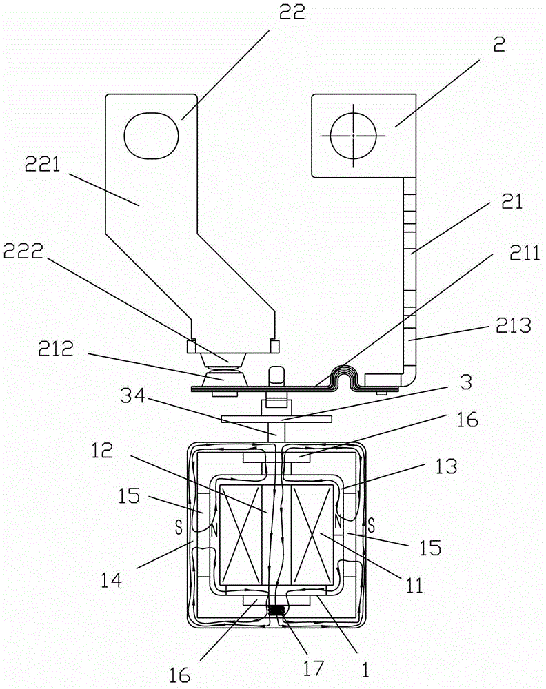
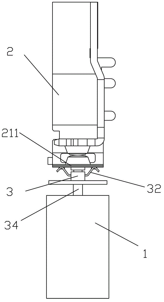
[0030] Embodiment one, see Figure 1 to Figure 7 As shown, the magnetic latching relay of the direct acting magnetic circuit structure of the present invention includes a magnetic circuit part 1, a contact part 2 and a push part 3; the push part 3 is connected between the magnetic circuit part 1 and the contact part 2; the contact part 2 Comprising a moving spring part 21 and a static spring part 22, the moving spring part 21 includes a moving reed 211 and a moving contact 212, and the static spring part 22 includes a static spring 221 and a static contact 222, and the moving spring 211 and the static spring 221 are respectively mounted on Corresponding positions, so that the movable contact 212 and the static contact 222 are adapted; the magnetic circuit part 1 includes a coil 11, an iron core 12, an inner yoke 13, an outer yoke 14, two permanent magnets 15 and two magnetic poles sheet 16; the inner yoke 13 and the outer yoke 14 are mouth-shaped structures respectively; the i...

Embodiment 2

[0047] Embodiment two, see Figure 8 As shown, the magnetic latching relay of the direct-acting magnetic circuit structure of the present invention is different from the first embodiment in that the magnetic latching relay has a left and right two-way structure, so the contact part includes two sets of moving spring parts 21 and static spring parts. Part 22 : fix the two ends of the iron core of the magnetic circuit part 1 with a corresponding piece of magnetic pole piece respectively through the threads of the connecting rods of the two sets of pushing parts 3 .


PUM


Abstract

The invention discloses a magnetic latching relay of a directly-operated type magnetic circuit structure. The magnetic latching relay comprises a magnetic circuit part, a contacting part and a pushing part. The magnetic circuit part comprises a coil, an iron core, an inner yoke, an outer yoke, two permanent magnets and two pole pieces. The inner yoke and the outer yoke are of an opening-shaped structure respectively. The iron core is arranged in the coil. The coil is arranged in the inner yoke in a sleeved mode. The outer yoke is arranged outside the inner yoke in a sleeved mode. The two pole pieces are arranged between the inner yoke and the outer yoke respectively. Movable gaps are arranged between the pole pieces, the inner yoke and the outer yoke. The two ends of the iron core penetrate out of the inner yoke respectively and are fixed with the corresponding pole pieces. The two permanent magnets are symmetrically arranged between the inner yoke and the outer yoke with the iron core as an axis respectively. The two faces of each permanent magnet are attached with the inner yoke and the outer yoke respectively. According to the magnetic latching relay, large driving power can be formed during relay coil electrifying, large retention force can be formed during relay coil outage, the magnetic latching relay has the advantages that magnetic disturbance resisting capacity is enhanced, product size is reduced, and cost is lowered.

Description

technical field [0001] The invention relates to a magnetic latching relay, in particular to a magnetic latching relay with a direct-acting magnetic circuit structure. Background technique [0002] The structure of the existing magnetic latching relay consists of a magnetic circuit system, a contact system, a driving part and a base. The magnetic circuit system generally consists of two basically symmetrical magnetic circuits, including stationary magnetizer parts, movable magnetizer parts and coils. The contact system includes a moving spring part and a static spring part. The pushing part is generally played by a push card. The relay coil passes the positive pulse voltage, the magnetic circuit system works, pushes the card to push the moving spring part, and makes the contacts contact, the relay operates, the coil passes the reverse pulse voltage, the magnetic circuit system works, pushes the card to push the moving spring part, and the contacts disconnected, the relay res...

Claims


Application Information

Patent Timeline
Patent Type & Authority Applications(China)
IPC IPC(8): H01H50/20
Inventor 施生圣钟叔明
Owner XIAMEN HONGFA ELECTRIC POWER CONTROLS
Why Eureka
Try Eureka