Guide rod and guide device

A guide rod and guide head technology, applied in the field of guide rods, can solve the problems of poor guidance accuracy, damage to copper tubes and fins, and inability to guide copper tubes, so as to prevent damage and avoid damage. Effect

Active Publication Date: 2017-01-25
GREE ELECTRIC APPLIANCES INC
View PDF8 Cites 0 Cited by
  • Summary
  • Abstract
  • Description
  • Claims
  • Application Information

AI Technical Summary

Problems solved by technology

The guiding device cannot effectively guide the two ends of the same copper tube or multiple copper tubes, so that the equipment may fail to guide and damage the copper tubes and fins during the process of passing through the tubes, and the guiding accuracy is very poor. Poor, the pipe threading process is not accurate, and there are quality risks

Method used


Image

  • Guide rod and guide device
  • Guide rod and guide device
  • Guide rod and guide device

Examples


Embodiment Construction

[0029] In order to solve the problems of poor guiding accuracy and imprecise pipe threading process, a guide rod and a guiding device are proposed to improve the accuracy of guiding and the precision of pipe threading process.

[0030] The above and other technical features and advantages of the present invention will be described in more detail below in conjunction with the accompanying drawings.

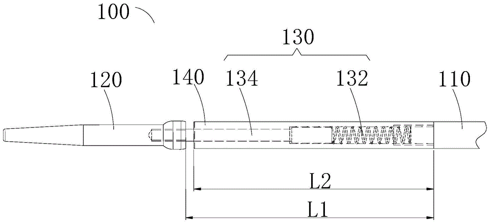
[0031] see figure 1 As shown, it is a schematic front view of the guide rod of the present invention. The guide rod 100 of the present invention includes a body 110 , a guide head 120 and an elastic connection assembly 130 . Both the body 110 and the guide head 120 are rod-shaped, and can be conveniently penetrated into the copper pipe to guide its axial position during use.

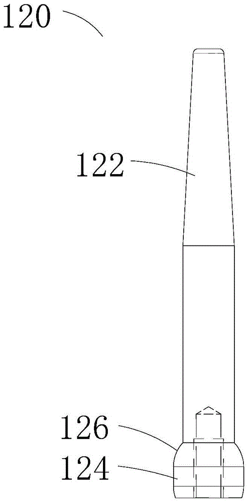
[0032] see figure 2 As shown, it is a schematic front view of the guide head of the guide rod of the present invention, the guide head 120 includes a larger end 124 and a smaller end 122, and the guide hea...


PUM


Abstract

The invention relates to a guide bar and a guide device. The guide bar comprises a body, a guide head and an elastic connection unit. The guide head has a large end and a small end and is symmetric about its axis. The elastic connection unit is elastic; length of the elastic connection unit is adjustable. Two ends of the elastic connection unit are connected to the body and the large end of the guide head respectively. Therefore, errors of raw materials are adapted, and guiding accuracy is improved.

Description

technical field [0001] The invention relates to the pipe threading technology, in particular to a guide device in the fin pipe threading equipment and a guide rod used therein. Background technique [0002] In the prior art, automatic pipe threading equipment uses guide rods to forcibly guide the copper pipes, and the guide rods are generally integrally formed of rigid materials. Due to the fact that the length of both ends of the U-shaped copper tube, the raw material used by the automatic tube threading equipment, may have a certain error, and when multiple copper tubes are placed in a row, there may also be a distance difference between the ends of all copper tubes. [0003] The above reasons lead to problems in the consistency of the contact between the guide rod and all U-shaped copper tubes. For the same U-shaped copper tube, when the end of one end reaches the end of the guide rod, the other end may not reach it. For multiple U-shaped copper tubes, some copper tubes ...

Claims


Application Information

Patent Timeline
Patent Type & Authority Patents(China)
IPC IPC(8): B23P19/00
CPCB23P19/00
Inventor 朱岳刚张保全邱雄胜尹显椿彭丹
Owner GREE ELECTRIC APPLIANCES INC
Why Eureka
Try Eureka