
Unbalance amount measuring device and method thereof

A measurement device and measurement method technology, applied in the direction of measurement device, static/dynamic balance test, machine/structural component test, etc. problems, to achieve the effect of reducing adverse effects, improving the accuracy of test data, and improving test efficiency

Active Publication Date: 2014-07-02
MESNAC
View PDF7 Cites 9 Cited by
  • Summary
  • Abstract
  • Description
  • Claims
  • Application Information

AI Technical Summary

Problems solved by technology

[0004] as attached figure 1 As shown, in the existing dynamic balancing equipment, round steel is usually used as the vibrating element (22), and the vibrating element (22) can form effective vibration in the 360-degree circumferential direction during the test process, so it is generally necessary to arrange the tie rod (23) to Balance the reverse tension formed by the drive belt (21) of the motor, and this part of the tension is inevitably disturbed by the vibration of the drive belt (21) when the tension is balanced, which will cause distortion of the detection data of the sensor (20) and increase the test error rate
[0005] In addition, the sensors (20) are installed between the vibrating shaft and the fixed plate in a vertical plane to form a line or a character. The sensor mounting screws will bear part of the gravity of the vibrating shaft of several hundred kilograms. prone to damage
At the same time, the deformation of the screw will directly affect the accuracy of the sensor's force perception, providing inaccurate data for subsequent quality ratings

Method used


Image

  • Unbalance amount measuring device and method thereof
  • Unbalance amount measuring device and method thereof
  • Unbalance amount measuring device and method thereof

Examples


Embodiment 1

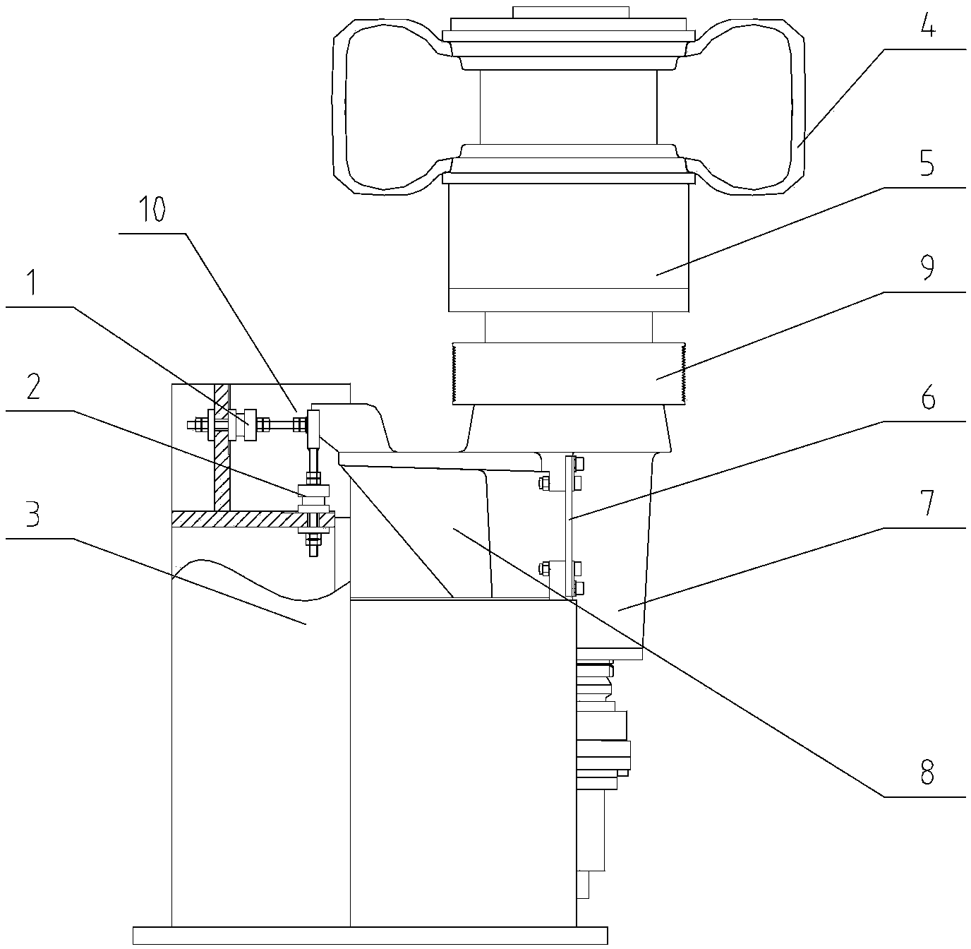
[0045] Example 1, such as Figure 2 to Figure 3 As shown, the described measuring device for unbalance mainly includes:

[0046] A vibrator 6 and a sensor group 10 are arranged between the fixed seat 3 and the rotating shaft housing 7, wherein,

[0047] The vibrating member 6 has a centrally symmetrical overall planar structure. In this embodiment, the vibrating member 6 is a rectangular flat plate structure, and one end of the vibrating member 6 along the direction of extending the axial center line 11 of the rotating shaft 5 is connected to the fixed seat 3 (this end is a fixed connection and there should be no vibration), and the other end is connected to the extension part 8 of the rotating shaft housing.

[0048] The sensor group 10 has a horizontal sensor 1 and a vertical sensor 2, the vertical sensor 2 is arranged parallel to the vibrating element 6, and the horizontal sensor 1 is perpendicular to the plane where the vibrating element 6 is located.

[0049] One end of...


PUM


Abstract

The invention discloses an unbalance amount measuring device and a method thereof. A flat-plate-type vibrating piece is arranged in the extension part of a dynamic balance testing device, and the flat-plate-type vibrating piece only vibrates in two orthogonal directions of a plane in which the vibrating piece is arranged. Therefore, irregular tremor effects generated by driving wheels are shielded, and rotation amplitude generated by unbalance and vibration data formed due to the self-weight of a detected tire and a rotation shaft are intensively transmitted to a sensor group so as to improve the accuracy of detection data and further improve unbalance mass detection and rating dimension. The measuring device comprises the vibrating piece and the sensor group, wherein the vibrating piece is connected between a fixed seat and a shell of the rotation shaft. Two connecting ends of the vibrating piece are arrayed along the extension direction of the axial center line of the rotation shaft. The sensor group is at least provided with a horizontal sensor and a vertical sensor. The vertical sensor is arranged in parallel with the vibrating piece and the horizontal sensor is perpendicular to the plane in which the vibrating piece is arranged.

Description

technical field [0001] The invention relates to a measuring device applied to tire dynamic balance unbalance and an improved measuring method based on the structural upgrade of the measuring device, which belongs to the fields of rubber machinery and industrial automation. Background technique [0002] In the process of manufacturing rubber tires, a series of testing items need to be carried out online, such as the unbalance test that must be carried out before the tire leaves the factory. Due to equipment tolerances and materials used, there are varying degrees of unevenness in the tire production process, that is, the cross section of the tire will not be completely circular. It is necessary to obtain its specific parameter indicators through the detection of unbalance, and then accurately judge the quality level of tire manufacturing. [0003] Based on the unbalanced quality inspection and rating of rubber tires, in the dynamic balance inspection equipment, it is necessa...

Claims


Application Information

Patent Timeline
Patent Type & Authority Applications(China)
IPC IPC(8): G01M1/22
Inventor 张艾贞咸龙新姜龙超刘军
Owner MESNAC
Learn More