
Optical time domain reflectometer based on double acoustic-optical modulators and common-mode rejection method of optical time domain reflectometer

A technology of optical time domain reflectometer and acousto-optic modulator, which is applied in the direction of transmitting sensing components with optical devices, can solve the problems of harsh and unfavorable phase measurement system noise suppression, avoid harsh restrictions, and improve signal amplitude and phase Measurement accuracy, effect of frequency reduction

Active Publication Date: 2014-07-02
WUHAN WUTOS
View PDF6 Cites 16 Cited by
  • Summary
  • Abstract
  • Description
  • Claims
  • Application Information

AI Technical Summary

Problems solved by technology

The patented technical solution uses a phase modulator to generate multiple frequency components for multiplexing measurement, and uses an acousto-optic modulator for frequency shifting and optical pulse generation. For data acquisition and signal post-processing sampling rate and data parallel processing hardware performance indicators The requirements are high, and the sampling rate of the acquisition card needs to be as high as 500MHz or more, which puts forward very strict requirements on the design of the hardware circuit, which is not conducive to the noise suppression of the phase measurement system

Method used


Image

  • Optical time domain reflectometer based on double acoustic-optical modulators and common-mode rejection method of optical time domain reflectometer
  • Optical time domain reflectometer based on double acoustic-optical modulators and common-mode rejection method of optical time domain reflectometer
  • Optical time domain reflectometer based on double acoustic-optical modulators and common-mode rejection method of optical time domain reflectometer

Examples


Embodiment Construction

[0039] In order to make the object, technical solution and advantages of the present invention clearer, the present invention will be further described in detail below in conjunction with the accompanying drawings and embodiments. It should be understood that the specific embodiments described here are only used to explain the present invention, not to limit the present invention.

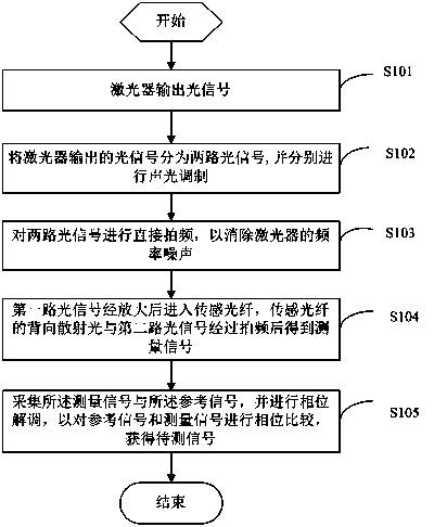
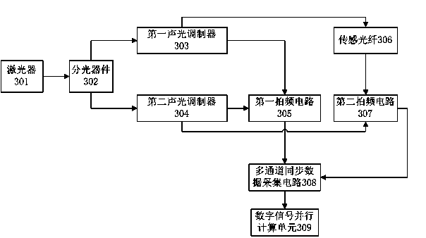
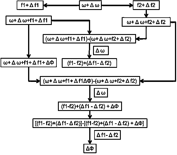
[0040] The embodiment of the present invention is based on the common-mode suppression method of the phase-sensitive optical time-domain reflectometer with dual acousto-optic modulators. By using two acousto-optic modulators and introducing a reference signal for common-mode suppression, the phase-sensitive optical time domain is reduced. Influence of laser frequency noise and acousto-optic modulator phase noise on measurement results in time domain reflectometer. Such as figure 1 As shown, the common-mode suppression method of the phase-sensitive optical time-domain reflectometer based on dual ac...


PUM


Abstract

The invention discloses an optical time domain reflectometer based on double acoustic-optical modulators and a common-mode rejection method of the optical time domain reflectometer. The method includes the following steps that a laser device outputs an optical signal; the optical signal is divided into two routes of optical signal bodies, and the optical signal bodies are modulated; direct frequency beating is conducted on the two routes of optical signal bodies so that frequency noise of the laser device can be eliminated and a reference signal can be generated; the first route of optical signal bodies enter a sensing optical fiber after being amplified, and a measurement signal is obtained after frequency beating is conducted on the back scattered light of the sensing optical fiber and the second route of optical signal bodies; the measurement signal and the reference signal are collected, phase demodulating is conducted, and phase comparison is conducted on the reference signal and the measurement signal to obtain a signal to be measured. The two acoustic-optical modulators are adopted, and by means of the method of conducting common-mode rejection by introducing the reference signal, influences of frequency noise of the laser device in the phase sensitive optical time domain reflectometer and frequency noise of the acoustic-optical modulators on the measurement result are reduced.

Description

technical field [0001] The invention relates to an optical time domain reflectometer, in particular to an optical time domain reflectometer based on a dual acousto-optic modulator and a common-mode suppression method thereof. Background technique [0002] Phase-sensitive optical time domain reflectometer (hereinafter referred to as Phase-OTDR) is a distributed optical fiber sensor based on Rayleigh scattering, which can remotely monitor the external dynamic physical quantities along the sensing optical fiber. Phase-OTDR needs to use a laser with a narrow linewidth (less than 10KHz) and a very small frequency drift as a light source, and obtains the environmental parameters at the disturbance position by detecting the change of the interference signal of the Rayleigh scattered light in the optical fiber in the region of the optical pulse width information (temperature, pressure, vibration, sound, etc.) and locate events by measuring the return time of light pulses. In additi...

Claims


Application Information

Patent Timeline
IPC IPC(8): G01D5/353
Inventor 闫奇众印新达谢竞
Owner WUHAN WUTOS
Learn More