
Direct pipe laying machine

A pipelayer, direct technology, applied in mining equipment, earthwork drilling, tunnels, etc., can solve the problems of small drilling diameter, low slag discharge efficiency, waste of construction time, etc., to improve construction efficiency and high degree of mechanical automation , the effect of easy maintenance

Active Publication Date: 2014-07-02
CHINA RAILWAY ENGINEERING EQUIPMENT GROUP CO LTD
View PDF6 Cites 11 Cited by
  • Summary
  • Abstract
  • Description
  • Claims
  • Application Information

AI Technical Summary

Problems solved by technology

[0002] Existing non-excavation equipment appeared in the 1970s. In order to meet the needs of gas, telecommunications or electric power projects such as crossing roads, railways, buildings, rivers, historic sites, and downtown areas, horizontal directional drills, horizontal auger drills, and impact drills have been produced. With the development of technology, horizontal directional drilling and pipe jacking machines have been widely used, but the former has a small drilling diameter and needs to repeatedly take over and discharge pipes. The efficiency of slag is low. The latter needs to harden a large area of ​​ground in advance, and excavate and build launching pits and receiving pits. Every time you advance, you need to re-connect the pipeline, re-dismantle and install electrical and hydraulic pipelines, etc., which waste a lot of construction time.

Method used


Image

  • Direct pipe laying machine
  • Direct pipe laying machine
  • Direct pipe laying machine

Examples


Embodiment Construction

[0024] The specific implementation manners of the present invention will be described in detail below in conjunction with the accompanying drawings.

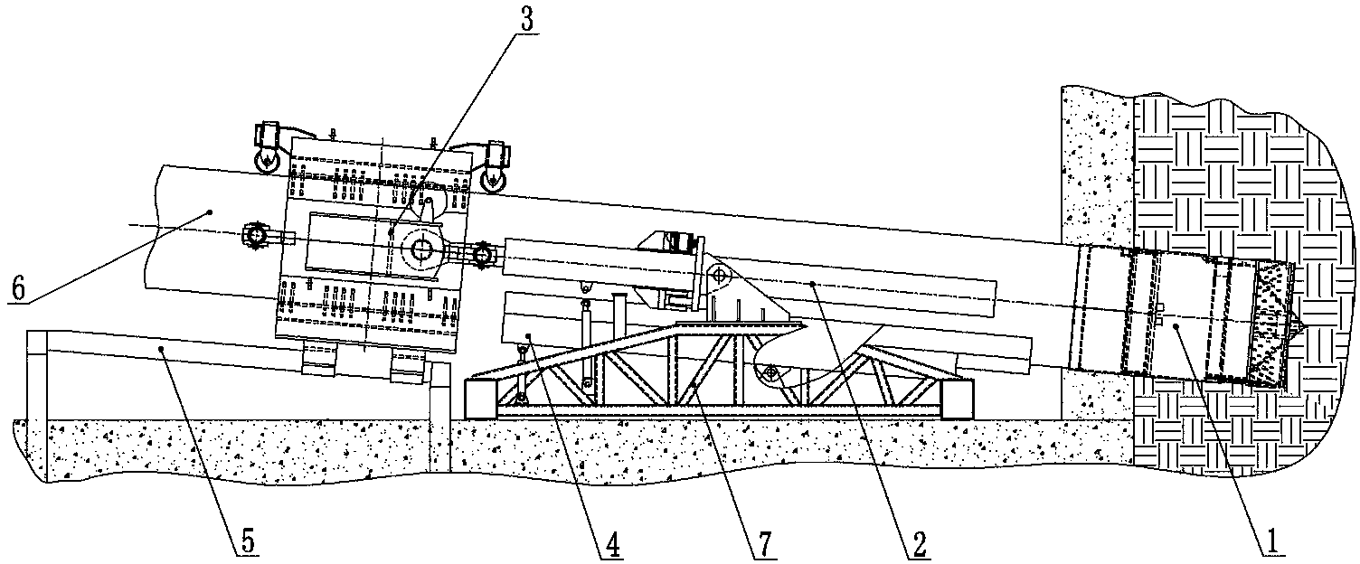
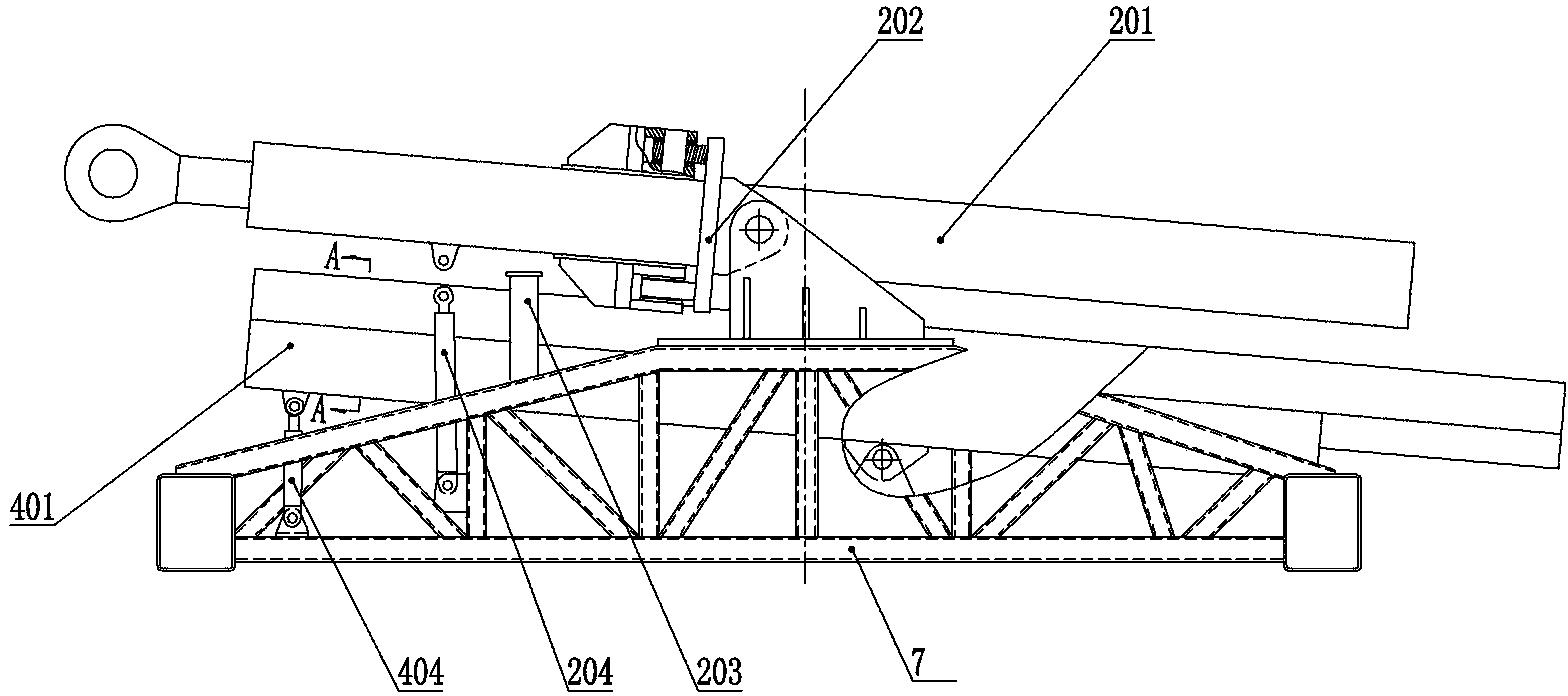
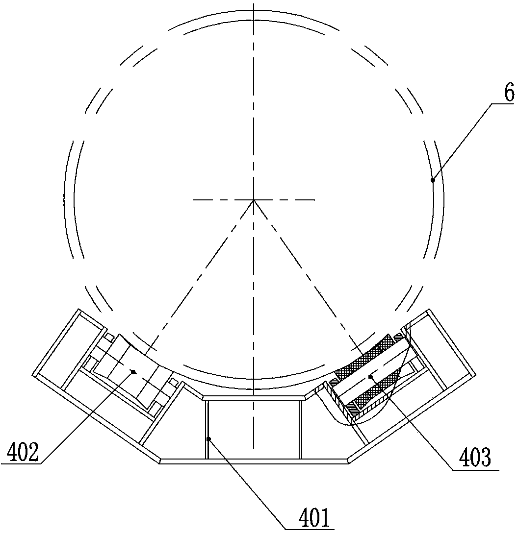
[0025] see Figure 1-Figure 6 , a direct pipe-laying machine, comprising an underframe 7, a roadheader 1 arranged at the front end of the underframe 7, a supporting device 4 arranged at the lower part of the roadheader 1 for supporting and guiding the roadheader 1, and a The pipeline 6, the clamping device 3 arranged at the back of the boring machine 1 to support the pipeline 6, and the propulsion device 2 arranged between the clamping device 3 and the supporting device 4, the supporting device 4 includes a The joist matching the pipeline 6, the joist includes a groove-shaped joist main body 401 and a rubber wheel 402 arranged in the groove for supporting the roadheader 1 or the pipeline 6, the rubber wheel 402 is connected with the mandrel 403 The joist main body 401 is connected, one end of the bottom of the joist main body 4...


PUM


Abstract

The invention belongs to the technical field of trenchless construction machinery, and discloses a direct pipe laying machine comprising a heading machine, a holding device, a pipeline connected to the rear end of the heading machine, a clamping device which is arranged on the rear portion of the heading machine and which supports the pipeline, and a propulsion device arranged between the clamping device and the holding device. The holding device comprises a holding beam, one end of the holding beam is hinged to a supporting post, and the other end of the holding beam is hinged to a holding beam positioning cylinder. The clamping device comprises an annular upper main frame and clamping cylinders which are connected through pins, the ends of the clamping cylinders are fixed with arc friction plates matching with the heading machine or pipeline, and a sliding lug is arranged on the lower portion of a lower main frame and slides on a guide rail arranged on the lower portion in a matching manner. The propulsion device comprises a base frame and two propulsion cylinders, and the other ends of the propulsion cylinders are hinged to connecting lugs arranged on the main frames of the clamping device.

Description

technical field [0001] The invention belongs to the technical field of trenchless engineering machinery, and in particular relates to a direct pipe laying machine. Background technique [0002] Existing non-excavation equipment appeared in the 1970s. In order to meet the needs of gas, telecommunications or electric power projects such as crossing roads, railways, buildings, rivers, historic sites, and downtown areas, horizontal directional drills, horizontal auger drills, and impact drills have been produced. With the development of technology, horizontal directional drilling and pipe jacking machines have been widely used, but the former has a small drilling diameter and needs to repeatedly take over and discharge pipes. The efficiency of slag is low. The latter needs to harden a large area of ​​ground in advance, and excavate and build launching pits and receiving pits. Every time the propulsion needs to be re-connected to the pipeline, re-dismantling and installing electr...

Claims


Application Information

Patent Timeline
IPC IPC(8): E21D9/00
Inventor 李建斌赵华张宁川肖威卓兴建王杜娟贾连辉蒲晓波董艳萍郑永光王双旺周倩
Owner CHINA RAILWAY ENGINEERING EQUIPMENT GROUP CO LTD
Learn More