
Tuned mass damper for controlling vertical high-frequency vibration of floors and manufacturing method thereof

A technology for tuning mass damping and high-frequency vibration. It is applied in building components and anti-vibration. It can solve the problems of high height and difficult to install inside the floor, poor device durability, and inability to completely separate the damping and stiffness of damping components, so as to improve the starting characteristics. And the effect of durability, material saving and reasonable stress

Active Publication Date: 2016-04-13
NORTH CHINA UNIV OF WATER RESOURCES & ELECTRIC POWER
View PDF5 Cites 0 Cited by
  • Summary
  • Abstract
  • Description
  • Claims
  • Application Information

AI Technical Summary

Problems solved by technology

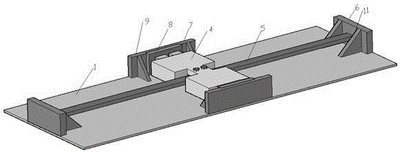
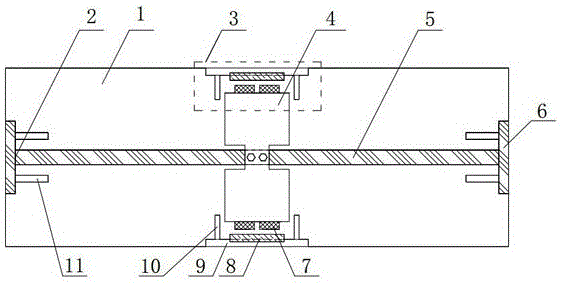
[0004] The technical problem to be solved by the present invention is to solve the problems that the vertical high-frequency tuned mass damper in the prior art is too high to be installed inside the floor, the damping and stiffness of the damping member cannot be completely separated, and the overall durability of the device is poor. A beam-type vertically tuned mass damper using a portal frame as a stiffness element and a manufacturing method thereof

Method used


Image

  • Tuned mass damper for controlling vertical high-frequency vibration of floors and manufacturing method thereof
  • Tuned mass damper for controlling vertical high-frequency vibration of floors and manufacturing method thereof
  • Tuned mass damper for controlling vertical high-frequency vibration of floors and manufacturing method thereof

Examples


Embodiment 1

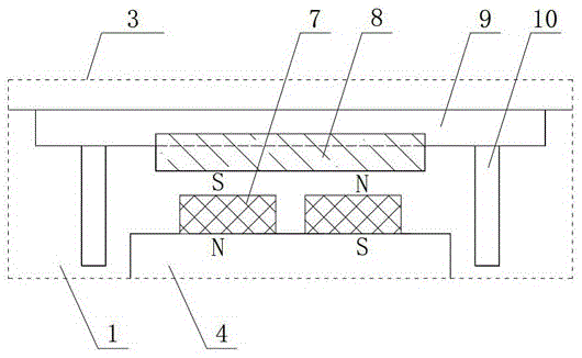
[0035] Embodiment one, see Figure 1 to Figure 3, the present invention includes a portal frame 2 , an eddy current damper 3 and a mass block 4 . The portal frame 2 is composed of a horizontal steel beam 5 and columns 6 fixed at both ends of the horizontal steel beam 5. The portal frame 2 is fixed on the concrete floor 16 through the bottom plate 1, and the mass block 4 is fixed on the portal frame 2 by bolts. The middle position of the horizontal steel beam 5; the eddy current damper 3 is provided with two sets, and each set is composed of a pair of rectangular permanent magnets 7 arranged alternately with N and S poles installed on the mass block 4 and a vertical vertical magnet welded on the bottom plate 1. Steel plate 9 and the conductor copper plate 8 that is installed on the inboard surface of vertical steel plate 9 are formed, and conductor copper plate 8 is thin in the middle along the vertical direction, and the upper and lower ends are thickened, keep equal with the ...

Embodiment 2

[0049] Embodiment two, see Figure 5 The difference between this embodiment and Embodiment 1 is that the bottom plate in this embodiment is a cross steel plate, which can reduce the proportion of the non-moving mass of the tuned mass damper, and is suitable for when the tuned mass damper is installed above or below the floor. That is, top-mounted installation or suspended installation, and other contents are the same as those in Embodiment 1, and will not be repeated here.


PUM


Abstract

The invention discloses a tuned mass damper for controlling vertical high-frequency vibration of floor slabs and a manufacturing method thereof. The tuned mass damper mainly comprises a gantry rigid frame, a weight and damping units; the gantry rigid frame is composed of pillars and a horizontal steel beam; the weight fixed on the horizontal steel beam is driven by vertical bending deformation of the horizontal steel beam to linearly reciprocate in the vertical direction; the weight is in a variable section form, thus the weight is centrally stressed on the horizontal steel beam, and height of the weight is reduced; eddy current damping units are used as damping elements, including two sets, used to keep balanced lateral stress; the whole damper is mounted inside a floor slab through a bottom steel plate, and partial rigidity of the floor slab is enhanced by the bottom steel plate. The tuned mass damper and the manufacturing method thereof have the advantages that high frequency required by the tuned massage damper for use in damping vertical vibration of floor slabs of industrial workshops is achieved, height of the damper is effectively reduced, and embedding the damper into the floor slab is facilitated.

Description

technical field [0001] The invention relates to a damper suitable for high-frequency vertical vibration control of industrial plant floors, in particular to a beam-type tuned mass damper for controlling vertical high-frequency vibrations of industrial plant floors and a manufacturing method thereof. Background technique [0002] The main reason for the floor vibration of existing industrial plants is that the vibration level caused by the machinery and equipment installed on the floor was underestimated in the design of the early industrial plants. In the calculation and analysis, the weight of the machinery and equipment was often multiplied by a certain power amplification factor to simulate the machinery and equipment. This leads to the fact that designers often control the deformation and stress of the structure (including the floor) by increasing the stiffness of the structure, ignoring the coupling vibration between the machine equipment and the floor, thus making the p...

Claims


Application Information

Patent Timeline
Patent Type & Authority Patents(China)
IPC IPC(8): E04B1/98
Inventor 汪志昊
Owner NORTH CHINA UNIV OF WATER RESOURCES & ELECTRIC POWER
Learn More