Material bag pouring structure of belt conveyor

A technology for belt conveyors and materials, applied in the direction of conveyor objects, transportation and packaging, etc., can solve problems such as high center of gravity, hidden safety hazards, etc., achieve simple and clear structure, avoid flattening and crushing, and have a wide range of applications

Inactive Publication Date: 2014-07-02
SHANGHAI TRIOWIN INTELLIGENT MACHINERY CO LTD
View PDF7 Cites 0 Cited by
  • Summary
  • Abstract
  • Description
  • Claims
  • Application Information

AI Technical Summary

Problems solved by technology

Due to the door frame structure, there will be safety hazards such as a high center of gravity during the adjustment process

Method used


Image

  • Material bag pouring structure of belt conveyor
  • Material bag pouring structure of belt conveyor
  • Material bag pouring structure of belt conveyor

Examples


Embodiment

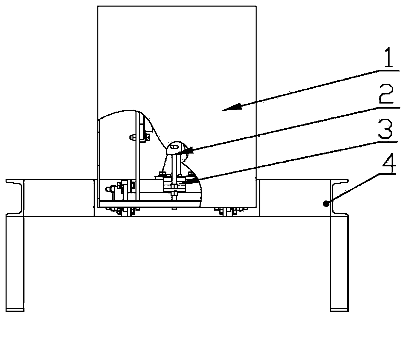
[0028] A belt conveyor material rewinding structure, such as Figure 1 to Figure 5 As shown, the structure includes a support 4, a control device, a push plate device and an induction device. The control device includes a cylinder 6 and a solenoid valve. The cylinder 6 is fixed on the rear side of the support 4. The solenoid valve is connected to the cylinder 6. The push plate 1 device includes Push pedal 1 and push pedal connecting rod 9, the bottom end of push pedal 1 rear side is rotatably connected with the front end of support 4 through belt square seat bearing 8, the middle part of push pedal 1 rear side is connected with cylinder 6 through push pedal connecting rod 9, The middle and lower part of the push plate 1 is provided with a hole. The sensing device includes a photoelectric sensor, an electric eye mounting frame 2 and a slow photoelectric fixing frame 3. Located at the same height as the hole on the push plate 1, the photoelectric sensor is connected to the solen...


PUM


Abstract

The invention relates to a material bag pouring structure of a belt conveyor. The material bag pouring structure of the belt conveyor comprises a support, a control device, a push plate device and an induction device, wherein the control device comprises an air cylinder and a solenoid valve, the air cylinder is fixed to the rear side of the support, the solenoid valve is connected with the air cylinder, the push plate device comprises a push plate and a push plate connecting rod, the bottom end of the rear side of the push plate is connected with the front end of the support in a rotating mode through a bearing with a square base, the middle of the rear side of the push plate is connected with the air cylinder through the push plate connecting rod, a hole is formed in the lower half portion of the push plate, the induction device comprises a photoelectric sensor, an electric eye mounting rack and a slow-photoelectricity fixing frame, the photoelectric sensor is fixed to the support through the electric eye mounting rack and the slow-photoelectricity fixing frame in sequence, the height of the photoelectric sensor is equal to that of the hole formed in the push plate, and the photoelectric sensor is connected with the solenoid valve. Compared with the prior art, the material bag pouring structure of the belt conveyor has the advantages of being simple in structure, safe, reliable, wide in application range, convenient to overhaul and the like.

Description

technical field [0001] The invention relates to a belt conveyor structure, in particular to a belt conveyor material reversing structure. Background technique [0002] At present, there are various defects in the material dumping mechanism of many belt conveyors. The most obvious manifestation is that there are restrictions on the size of the material, and the phenomenon that the material is easily squeezed and collided during the reciprocating movement of the push plate, thereby damaging the material and affecting production efficiency. [0003] Relevant documents also disclose some conveyor material pouring mechanisms that adjust the specifications and sizes of materials, but their structures are cumbersome and require manual operations from time to time, which greatly increases the cost of input and causes waste of manpower and material resources. If the material is dense, there will be phenomena such as jamming and scraping. Due to the use of the door frame structure, ...

Claims


Application Information

Patent Timeline
Patent Type & Authority Applications(China)
IPC IPC(8): B65G47/24
Inventor 曾庆贵李文艺童上高
Owner SHANGHAI TRIOWIN INTELLIGENT MACHINERY CO LTD
Why Eureka
Try Eureka