Production system and production method of optical display device

An optical display and production system technology, applied in optics, nonlinear optics, instruments, etc., can solve problems such as easy dust adhesion and poor bonding

Active Publication Date: 2016-06-08
SUMITOMO CHEM CO LTD
View PDF8 Cites 0 Cited by
  • Summary
  • Abstract
  • Description
  • Claims
  • Application Information

AI Technical Summary

Problems solved by technology

[0009] Again, before the optical member is bonded to the liquid crystal panel, dust is suppressed from adhering to the liquid crystal panel by static electricity removal of the liquid crystal panel, etc., but there is also the following problem: since the bonding surface of the optical member bonded to the liquid crystal panel has Adhesive, so dust is easy to adhere to, which becomes a cause of poor bonding

Method used


Image

  • Production system and production method of optical display device
  • Production system and production method of optical display device
  • Production system and production method of optical display device

Examples


no. 1 approach )

[0047] Hereinafter, a first embodiment of the present invention will be described with reference to the drawings. In this embodiment, as a production system of an optical display device, a film bonding system constituting a part thereof will be described.

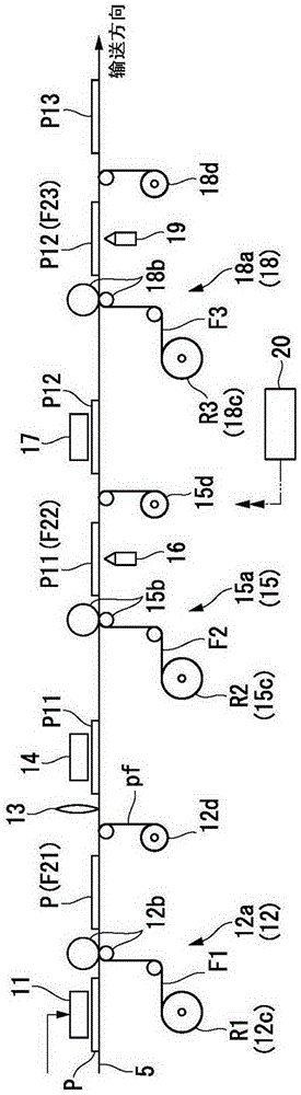
[0048] In particular, as described in detail below, in the film bonding system of the first embodiment, the bonding devices 12, 15, 18 and the cutting devices 16, 19 are arranged below the roller conveyor 5 (line), The cutting device 13 is arranged above the roller conveyor 5 .

[0049] figure 1 It shows the schematic structure of the film bonding system 1 of this embodiment. The film bonding system 1 bonds film-shaped optical members such as polarizing films, retardation films, and brightness enhancement films to panel-shaped optical display components such as liquid crystal panels and organic EL panels. The film bonding system 1 manufactures the optical member bonding body containing the said optical display component ...

no. 2 approach )

[0115] Hereinafter, a second embodiment of the present invention will be described with reference to the drawings. In this embodiment, as a production system of an optical display device, a film bonding system constituting a part thereof will be described.

[0116] In the second embodiment, the same symbols are assigned to the same components as those in the first embodiment, and descriptions thereof are omitted or simplified.

[0117] In particular, as described in detail below, in the film bonding system of the second embodiment, the bonding devices 112, 115, 118 and the cutting devices 116, 119 are arranged on the roller conveyor 105, and the cutting device 113 It is arranged under the roller conveyor 105 .

[0118] Figure 13 It shows the schematic structure of the film bonding system 101 of this embodiment. The film bonding system 101 bonds a film-shaped optical member such as a polarizing film, a retardation film, or a brightness enhancement film to a panel-shaped opt...


PUM


Abstract

This production system for an optical display device which is formed by affixing an optical member to an optical display component comprises the following: an affixing device that, while unwinding, with respect to a plurality of optical display components conveyed on a line, a band-shaped optical member sheet having a width greater than that of the display region of the optical display components from an original material roll in the component width direction that is orthogonal to the conveyance direction of the optical display components, thus affixing the plurality of optical display components to the optical member sheet and forming an affixed sheet; and a cutting device that cuts and separates an opposing portion of the optical member sheet that opposes the display region from the surplus portion positioned outside of the opposing portion, and cuts out from the optical member sheet optical members having a size which corresponds to the display region, thereby cutting from the affixed sheet an optical member affixed body that includes a single optical display component and the optical member overlapping that optical display component.

Description

technical field [0001] The present invention relates to a production system and production method of optical display devices such as liquid crystal displays. [0002] The present invention claims priority based on Japanese Patent Application No. 2011-253885 filed on November 21, 2011 and Japanese Patent Application No. 2011-253886 filed on November 21, 2011, the contents of which are incorporated herein. Background technique [0003] Conventionally, in the production system of optical display devices such as liquid crystal displays, optical members such as polarizers bonded to liquid crystal panels (optical display components) are cut from long films into sheets of a size suitable for the display area of ​​the liquid crystal panel. It is bonded to a liquid crystal panel (for example, refer to Patent Document 1). [0004] prior art literature [0005] patent documents [0006] Patent Document 1 Japanese Patent Application Laid-Open No. 2003-255132 Contents of the inventi...

Claims


Application Information

Patent Timeline
Patent Type & Authority Patents(China)
IPC IPC(8): G09F9/00G02B5/30G02F1/13
CPCG02F1/133528G02F1/13363G02F1/133322
Inventor 藤井干士土冈达也
Owner SUMITOMO CHEM CO LTD
Why Eureka
Try Eureka