
Organic light emitting diode display array

A technology of light-emitting diodes and display arrays, applied in static indicators, instruments, etc., can solve problems such as affecting the display performance of pixel units, laying five signal lines horizontally, etc., to save wiring space and reduce wiring density.

Active Publication Date: 2014-06-25
SHANGHAI TIANMA MICRO ELECTRONICS CO LTD
View PDF7 Cites 16 Cited by
  • Summary
  • Abstract
  • Description
  • Claims
  • Application Information

AI Technical Summary

Problems solved by technology

In a design with high pixel density, due to the small area of ​​the pixel unit, it is difficult to lay out five signal lines laterally in the area of ​​each pixel unit. It is necessary to modify the driving circuit in the sub-pixel to reduce the need for horizontal wiring, but modify the pixel compensation The reduction of horizontal wiring in the circuit will affect the display performance of the pixel unit

Method used


Image

  • Organic light emitting diode display array
  • Organic light emitting diode display array
  • Organic light emitting diode display array

Examples


Embodiment Construction

[0046] The technical solutions of the present invention will be further described below in conjunction with the accompanying drawings and through specific implementation methods.

[0047] Figure 4 It is a schematic circuit diagram of the OLED display array according to the first embodiment of the present invention. like Figure 4 As shown, the organic light emitting diode display array 40 includes a substrate 41, a plurality of organic light emitting diode macro pixel units 400 formed on the substrate in an array, and a plurality of organic light emitting diode macro pixel units arranged between the plurality of organic light emitting diode macro pixel units. A reset scan line 42 for transmitting a reset scan signal, a data line 43 intersecting the scan line, and a light-emitting trigger signal line 44 for transmitting a light-emitting trigger signal.

[0048] In the present invention, "macro pixel unit" refers to a pixel unit or a combination of pixel units including at le...


PUM


Abstract

The invention discloses an organic light emitting diode display array. According to the organic light emitting diode display array, through changing the time sequence control relationship and circuit connection relationship of organic light emitting diode pixel units, organic light emitting diode sub pixels of adjacent lines can share signals of scanning lines arranged in the middle of the two. On the premise of not reducing the performances of a pixel compensation circuit, wiring of N-1 scanning lines can be reduced for N lines of sub pixel unit arrays, wiring density can be greatly reduced, and the wiring space is saved.

Description

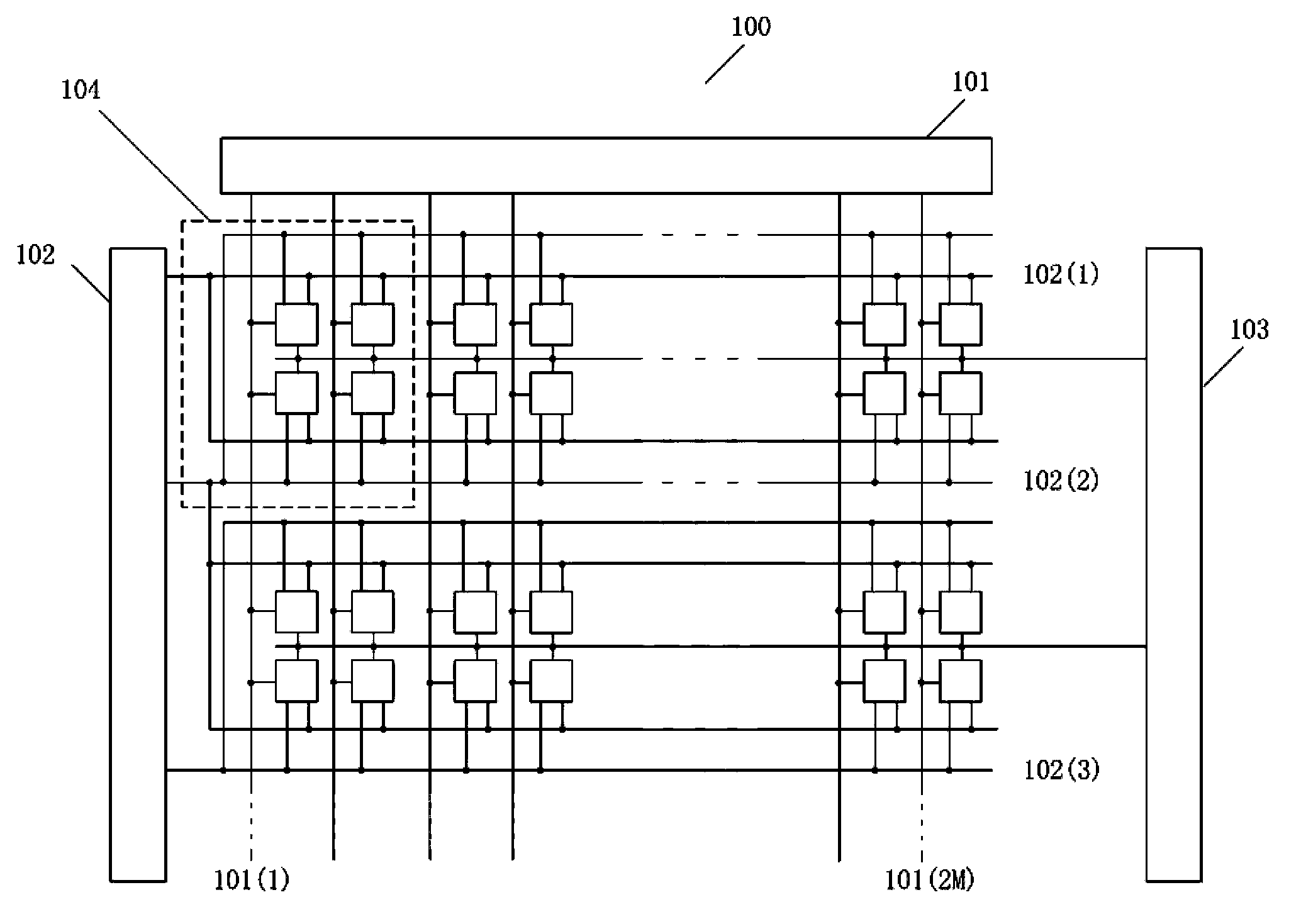
technical field [0001] The invention relates to the field of organic light emitting diode displays, in particular to an organic light emitting diode display array. Background technique [0002] Organic light-emitting diodes (OLEDs) are widely used in lighting and display fields due to their low voltage requirements and high power-saving efficiency, fast response, light weight, thin thickness, simple structure, and low cost. [0003] figure 1 It is a schematic circuit diagram of an existing OLED display device. like figure 1 As shown, the organic light emitting diode display device 100 includes a data line controller 101, a scan line controller 102, a light-emitting trigger signal controller 103, and an organic light emitting diode display array. The organic light emitting diode display array includes a substrate and an N×M array The organic light emitting diode pixel units 104 arranged on the substrate, each organic light emitting diode pixel unit 104 includes four sub-pi...

Claims


Application Information

Patent Timeline
Patent Type & Authority Applications(China)
IPC IPC(8): G09G3/32G09G3/3208
Inventor 顾寒昱
Owner SHANGHAI TIANMA MICRO ELECTRONICS CO LTD
Learn More