
air conditioner

A technology for air conditioners and humidifiers, which is applied in air conditioning systems, air humidification systems, and high-efficiency adjustment technologies, can solve the problems of small adjustment range, low air relative humidity, humidification range, and poor humidification effect, and achieves perfect effect. The effect of humidity equalization

Active Publication Date: 2018-07-10
GREE ELECTRIC APPLIANCES INC
View PDF5 Cites 0 Cited by
  • Summary
  • Abstract
  • Description
  • Claims
  • Application Information

AI Technical Summary

Problems solved by technology

[0003] Generally, when the indoor humidity is low, the relative humidity of the outdoor air is often low, so the range of humidity adjustment in this way is small, and when the outdoor air is relatively dry, it cannot even play a role in regulating humidity.
[0004] Therefore, at present, the humidification function of the existing room air conditioners cannot reach the desired humidification effect, and the humidification range and humidification effect of the environment are not good.

Method used


Image

  • air conditioner
  • air conditioner
  • air conditioner

Examples


Embodiment 1

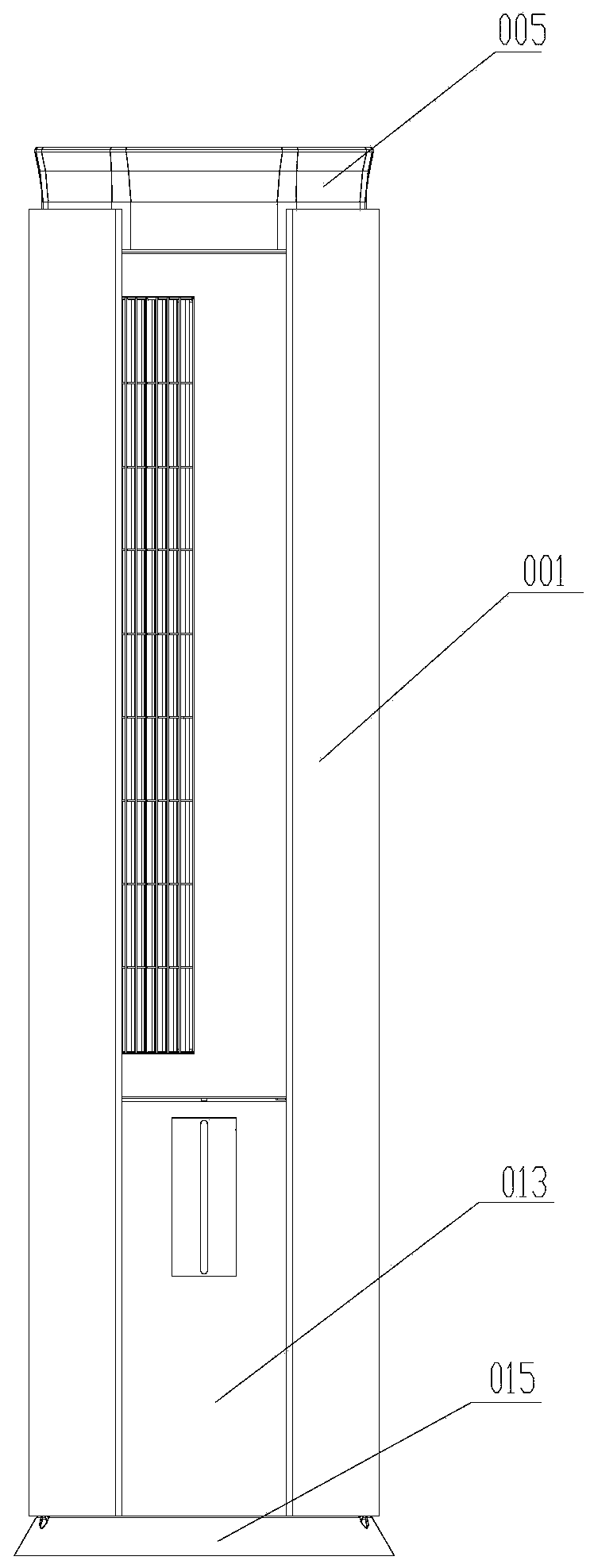
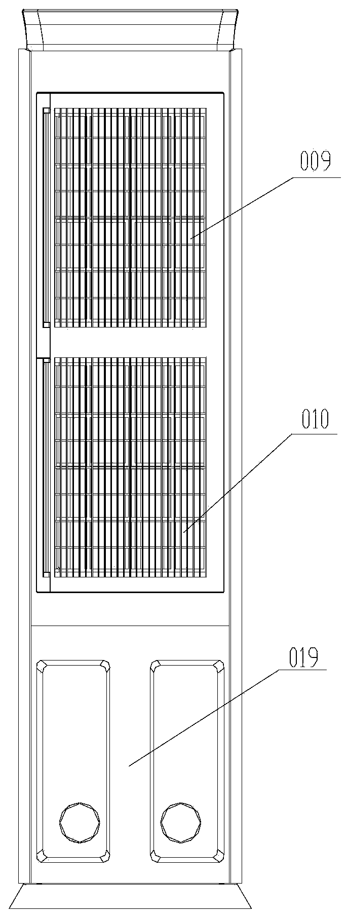
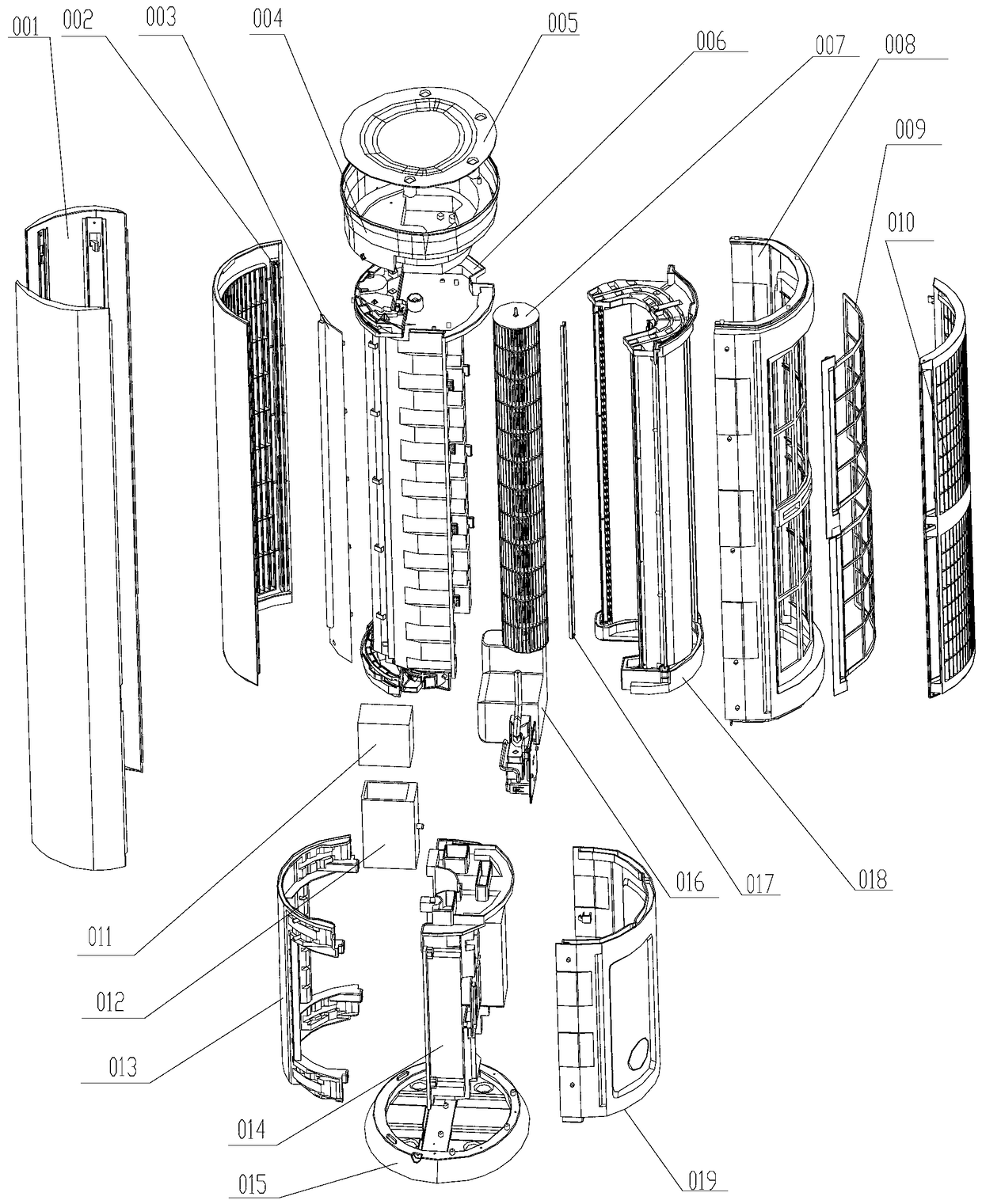
[0035] Such as figure 1 , 2 , as shown in 3, figure 1 , 2 It is the appearance of the complete machine of the vertical air conditioner in this embodiment. From this figure, it can be seen that the appearance of the complete machine is generous, clean and tidy, and occupies a small space. image 3 It is the exploded view of the complete machine of the vertical air conditioner of the present embodiment.

[0036] Preferably, the air conditioner is a column structure, and the body of the air conditioner includes: decorative panels 001 on both sides, a front door 013 at the front, a chassis 015 at the bottom, a top cover 005 at the top, and a rear side rear shell 019 and air intake bracket 008, the air intake panel 010 of the air conditioner is arranged on the air intake bracket 008, and the filter screen 009 of the air conditioner is fixed in the air intake panel 010; the air conditioner The air outlet panel 002 is arranged on the front door 013.

[0037] Such as image 3 As...

Embodiment 2

[0049] Such as figure 2 As shown, the difference between this embodiment and the first embodiment is that the connecting pipe is a pipe with a spiral structure, which surrounds the outer circumference of the cross-flow fan blade. Other features in this embodiment are the same as those in Embodiment 1, and will not be repeated here.

Embodiment 3

[0051] Such as image 3 As shown, the difference between this embodiment and the first embodiment is that the connecting pipe is a pipe with a broken line structure, and is located beside the cross-flow fan blade. Other features in this embodiment are the same as those in Embodiment 1, and will not be repeated here.


PUM


Abstract

The invention provides an air conditioner which comprises a ventilation assembly, a water storage tank, a humidifier and a mist spray device. The humidifier comprises a box and an atomizing device, and the atomizing device is arranged in the box; a water outlet of the water storage tank is communicated with a water inlet of the humidifier; the mist spray device is connected with a mist spray outlet of the humidifier, comprises more than one mist spray nozzle and is communicated with an exhaust channel of the ventilation assembly; water mist generated by the mist spray device can be sprayed out of air outlets of the ventilation assembly by the aid of the mist spray nozzles. The air conditioner has the advantages that the indoor humidity can be balanced when the air conditioner runs, and accordingly a balanced and comfortable humidity effect of an indoor environment can be realized; the mist spray device of the air conditioner comprises a connecting pipe and the multiple mist spray nozzles arranged on the connecting pipe, the ends of the connecting pipe are connected with mist spray outlets of the humidifier, accordingly, the water mist generated by the mist spray device can be selectively sprayed out of the air outlets along the upper, middle and lower directions by the aid of the multiple mist spray nozzles, and the humidification range and a humidification effect can be optimized.

Description

technical field [0001] The invention relates to the technical field of air conditioners, in particular to an air conditioner with humidification function. Background technique [0002] The comfort of air conditioning is not only related to temperature, but also has a lot to do with the relative humidity in the room. In autumn and winter, the ambient air is relatively dry. When the air conditioner is running, the indoor air will be circulated faster and the air will be drier, making users feel uncomfortable. Therefore, many high-end air conditioners now have a certain degree of humidity adjustment function in addition to temperature adjustment. At present, there are two main technical solutions for air conditioners that can adjust humidity: one is to add an adsorption wheel on the outdoor side, and the adsorption chamber The water vapor in the outside air is discharged into the room through the pipe, increasing the humidity of the room, and there are certain defects: [000...

Claims


Application Information

Patent Timeline
Patent Type & Authority Patents(China)
IPC IPC(8): F24F1/00F24F6/14
CPCY02B30/70
Inventor 孟宪运张辉陈绍林丘晓宏朱江伟孔环灵文超张玉忠陈国豪朱林赖桂枝
Owner GREE ELECTRIC APPLIANCES INC
Learn More