Tamper hydraulic system and construction machinery

A technology of hydraulic system and rammer, which is applied in the direction of mechanical equipment, infrastructure engineering, fluid pressure actuation device, etc., can solve the problems of hammering efficiency drop, difficulty in controlling lifting oil pressure release time, slow pressure drop, etc., to achieve reduction The effect of hydraulic shock

Active Publication Date: 2016-05-11
SANY AUTOMOBILE HOISTING MACHINERY
View PDF9 Cites 0 Cited by
  • Summary
  • Abstract
  • Description
  • Claims
  • Application Information

AI Technical Summary

Problems solved by technology

[0006] However, in the above scheme, it is difficult to control the pressure release time of the rod cavity of the lifting oil 1'. If a damping hole with a small damping value is used, the pressure in the rod cavity will drop too fast, and the entire hydraulic system will produce severe hydraulic shock. Using a damping hole with a large damping value, the pressure drop in the rod chamber is too slow, and the hammering efficiency is reduced

Method used


Image

  • Tamper hydraulic system and construction machinery
  • Tamper hydraulic system and construction machinery
  • Tamper hydraulic system and construction machinery

Examples


Embodiment Construction

[0039] It should be pointed out that the description and sequence of specific structures in this section are only descriptions of specific embodiments, and should not be considered as limiting the protection scope of the present invention. In addition, the embodiments in this section and the features in the embodiments can be combined with each other under the condition of no conflict.

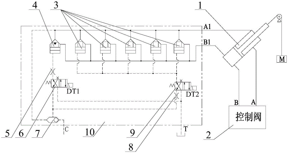
[0040] Please also refer to Figure 2 to Figure 5 , the embodiments of the present invention will be described in detail below in conjunction with the accompanying drawings.

[0041] combine figure 2 As shown, the tamper hydraulic system of the first embodiment includes a lift cylinder 1, a control valve 2, a switch cartridge valve 3, a buffer cartridge valve 4, a first damper 5, a second reversing valve 6, a shuttle valve 7, a second Two dampers 8, the first reversing valve 9 and the oil tank.

[0042] Among them, the working oil ports A and B of the control valve 2 are respectively conne...


PUM


Abstract

The invention discloses a pounder hydraulic system and engineering machinery. The pounder hydraulic system comprises a lifting oil cylinder, switch cartridge valves, a first reversing valve, an oil tank, a buffer cartridge valve, a second reversing valve and a first damper, wherein a first oil port and a second oil port of the buffer cartridge valve are respectively connected with a rod cavity and a rodless cavity of the lifting oil cylinder, a control oil port of the buffer cartridge valve is optionally connected with one of the rod cavity of the lifting oil cylinder and the oil tank through the second reversing valve, the first damper is arranged on an oilway between the control port of the buffer cartridge valve and the second reversing valve or arranged on an oilway between the second reversing valve and the rod cavity of the lifting oil cylinder or on an oilway between the second reversing valve and the oil tank. By the pounder hydraulic system, hydraulic impact under the condition of pounder dropping can be effectively reduced, pressure variations of the rod cavity of the lifting oil cylinder can be accurately controlled, and unlimited release of the pressure is realized. Besides, weight can quickly fall after the pressure is released, and pounding efficiency is improved.

Description

technical field [0001] The invention relates to the technical field of rammer control, in particular to a rammer hydraulic system and engineering machinery. Background technique [0002] As a kind of engineering machinery used for impact compaction of materials or foundations, rammer pile machinery is widely used in the construction process of industrial and civil buildings, warehouses, yards, docks, airports, road and railway subgrades, etc. , the basic principle is to lift the weight to a certain height, and then hammer the ground through the free fall of the weight. [0003] Existing tamper hydraulic systems generally use motors or oil cylinders to realize heavy lifting and falling conditions. Relatively speaking, hydraulic systems using motors as actuators have large internal leakage of high-pressure oil, high energy consumption, and high efficiency. And other shortcomings, and the method of using oil cylinder to quickly lift and drop heavy objects has low energy consum...

Claims


Application Information

Patent Timeline
Patent Type & Authority Patents(China)
IPC IPC(8): F15B13/02F15B11/02E02D3/046
Inventor 易迪升彭勇王鹏程
Owner SANY AUTOMOBILE HOISTING MACHINERY
Why Eureka
Try Eureka