Actuation device for actuating switching elements

A technology for operating devices and shifting components, applied in the direction of valve operating/release devices, valve devices, electromechanical devices, etc., can solve problems such as loss, achieve high valve power, avoid mechanical friction loss, and avoid the effect of plug connection

Inactive Publication Date: 2014-06-18
ZF FRIEDRICHSHAFEN AG
View PDF9 Cites 5 Cited by
  • Summary
  • Abstract
  • Description
  • Claims
  • Application Information

AI Technical Summary

Problems solved by technology

This pressure has to be loaded by the hydraulic pump driven by the car motor, resulting in losses

Method used


Image

  • Actuation device for actuating switching elements
  • Actuation device for actuating switching elements
  • Actuation device for actuating switching elements

Examples


Embodiment Construction

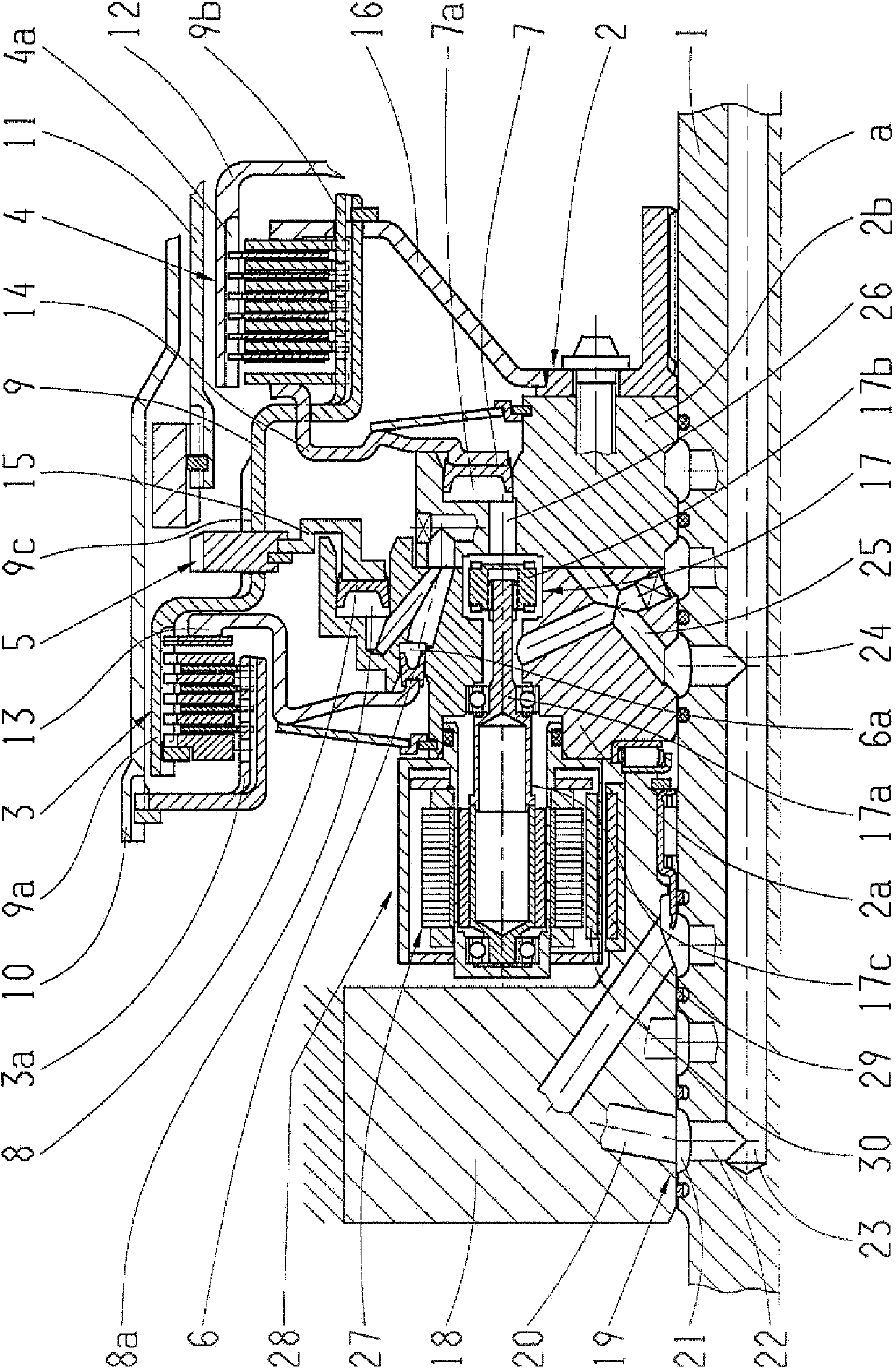
[0029] figure 1 An actuating device according to the invention for an automatic transmission of a motor vehicle is shown, which has a drive shaft 1 on which a so-called functional carrier 2 with an axis of rotation a is arranged in a rotationally fixed manner. A total of three shifting elements, namely the first plate clutch 3 , the second plate clutch 4 and the jaw clutch 5 , are connected via the functional carrier 2 . Hydraulically actuatable shifting devices (designed as piston / cylinder units 6 , 7 , 8 ) are assigned to the shifting elements 3 , 4 , 5 . The shifting devices 6 , 7 each have an annular annular cylinder configured as a pressure chamber 6 a , 7 a which is arranged in the functional carrier 2 . The shifting elements 3 , 4 , 5 are connected on the drive side via a common combined disc / dog carrier 9 , which is based on the first disc clutch 9 as an outer disc carrier 9 a and based on the second disc clutch 4 It is an inner disc carrier 9 a and, in the case of t...


PUM


Abstract

The invention relates to an actuation device for actuating at least one switching element (3, 4, 5) that can be switched via a switching device (6, 7, 8), the switching device (6, 7, 8) comprising a pressure chamber (6a, 7a, 8a) with a feed (26) for a pressure medium and a shut-off valve (17). According to the invention, the shut-off valve (17) can be electrically actuated and is connected to the at least one switching element (3, 4, 5) in a rotationally fixed manner, and the electrical energy for actuating the shut-off valve (17) can be supplied in a contactless manner.

Description

technical field [0001] The invention relates to an actuating device according to the preamble of claim 1 for actuating at least one shifting element which can be shifted by means of a shifting device, and to the use of the actuating device. Background technique [0002] In today's vehicle transmissions, especially automatic transmissions, the driving is shifted via shifting elements (ie clutches or brakes) designed as disc shifting elements or jaw shifting elements. The shifting usually takes place hydraulically, that is to say by means of a shifting device in the form of a piston / cylinder unit, which is supplied with pressurized oil. This pressurized oil is conveyed by the pump and conducted via an oil supply from the transmission housing body via a so-called rotary oil supply into the rotating drive shaft and from there to the shifting device. Through the hydraulic circuit, that is to say the output of the transmission oil pump, the sealing points, the pressure drop in th...

Claims


Application Information

Patent Timeline
Patent Type & Authority Applications(China)
IPC IPC(8): F16D25/04F16D25/10F16K31/04F16K31/50H02K11/00
CPCH02K16/00H02K11/0094F16D48/0206F16H61/68F16D2048/0278F16H2708/20F16H2708/22F16D25/044F16D2048/0221Y10T74/19251F16D25/10F16D25/0638
Inventor 马蒂亚斯·赖施拉尔夫·德雷布霍尔茨
Owner ZF FRIEDRICHSHAFEN AG
Why Eureka
Try Eureka