Multi-channel adaptive load led constant current drive circuit

A self-adaptive load, constant current drive technology, applied in the direction of lamp circuit layout, electric light source, lighting devices, etc., can solve the problems of small size, low constant current precision, driving LED can not be changed at will, to achieve simple circuit structure, constant The effect of high flow accuracy and low cost

Active Publication Date: 2016-09-14
WUHAN JINGCE ELECTRONICS GRP CO LTD
View PDF5 Cites 0 Cited by
  • Summary
  • Abstract
  • Description
  • Claims
  • Application Information

AI Technical Summary

Problems solved by technology

At present, LED drive generally adopts linear constant current power supply or switching power supply drive mode. The linear constant current power supply circuit has a simple structure and high constant current precision, but it requires an external circuit to provide a power MOS tube that can not only meet the normal light emission of the LED, but also meet the power requirements. (Transistor) The DC voltage working in the saturation region, once the given voltage is fixed, the number of LEDs driven cannot be changed at will; in addition, the switching power supply can self-adjust the output voltage and is small in size, but its constant current accuracy is lower than that of the linear power supply

Method used


Image

  • Multi-channel adaptive load led constant current drive circuit
  • Multi-channel adaptive load led constant current drive circuit
  • Multi-channel adaptive load led constant current drive circuit

Examples


Embodiment Construction

[0013] The present invention will be further described in detail below in conjunction with the accompanying drawings and specific embodiments.

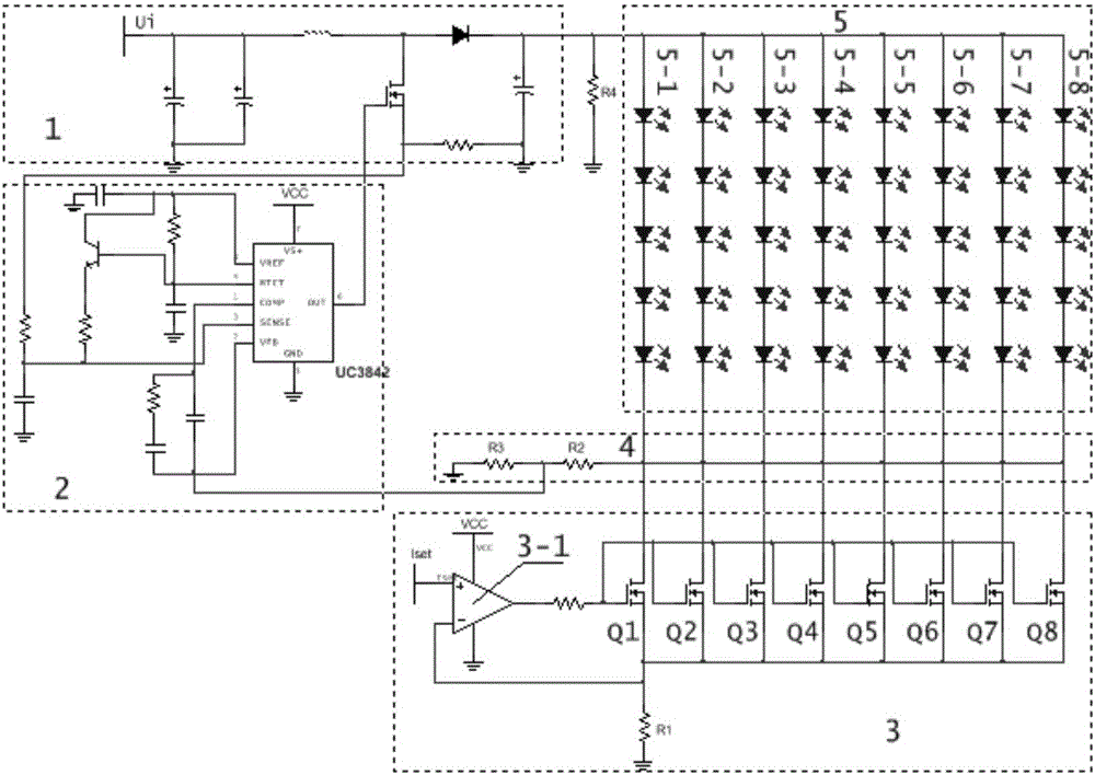
[0014] like figure 1 As shown, the multi-channel self-adaptive load LED constant current drive circuit provided by the present invention includes a boost circuit 1 , a control circuit 2 , a closed-loop constant current mirror drive circuit 3 and a sampling circuit 4 . The closed-loop constant-current mirror drive circuit 3 includes an operational amplifier 3-1, power MOS transistors Q1-Qn equal in number to the number of LED lamp string groups 5, and a current-limiting resistor R1. The sampling circuit 4 includes sampling resistors R2 and R3 connected in parallel. The output end of the boost circuit 1 is connected to the anode of each LED light string 5-1~5-n in the LED light string group 5, and the cathode of each LED light string 5-1~5-n is respectively connected to a corresponding power The drains of MOS transistors Q1~Qn are con...


PUM


Abstract

The invention discloses an LED constant-current driving circuit of multi-path self-adaptive loads. The LED constant-current driving circuit comprises a booster circuit providing positive electrode driving voltage for LED string lamps, a control circuit, a closed loop constant-current mirror driving circuit and a sampling circuit. The closed loop constant-current mirror driving circuit comprises an operational amplifier, power MOS transistors and current limiting resistors R1. The output end of the booster circuit is connected with the positive electrodes of each path of LED string lamps, the negative electrodes of each path of LED string lamps are connected with a drain electrode of one corresponding power MOS transistor, the gate electrode of each power MOS transistor is connected with the output end of the operational amplifier, the source electrode of each power MOS transistor is grounded through one current limiting resistor R1, and one end, connected with the corresponding power MOS transistor, of each current limiting resistor R1 is connected with the reverse input end of the operational amplifier. The output end of the closed loop constant-current mirror driving circuit is connected with the sampling circuit, the control circuit is respectively connected with the sampling circuit and the booster circuit, and the control circuits controls the output voltage of the booster circuit according to the voltage value acquired by the sampling circuit. The LED constant-current driving circuit is high in constant-current precision and capable of automatically regulating the driving voltage and driving multiple paths of LED string lamps at the same time.

Description

technical field [0001] The invention relates to the technical field of LED driving, in particular to a multi-channel self-adaptive load LED constant current driving circuit. Background technique [0002] LED lamps have attracted widespread attention due to their long life, stability and reliability, high luminous efficiency, low power consumption and fast lighting speed. LED lamps are considered to become the fourth generation of general lighting sources. An indispensable part of LED products directly affects the life and reliability of LED products. At present, LED drive generally adopts linear constant current power supply or switching power supply drive mode. The linear constant current power supply circuit has a simple structure and high constant current precision, but it requires an external circuit to provide a power MOS tube that can not only meet the normal light emission of the LED, but also meet the power requirements. (Transistor) The DC voltage working in the sa...

Claims


Application Information

Patent Timeline
Patent Type & Authority Patents(China)
IPC IPC(8): H05B37/02
CPCY02B20/40
Inventor 彭骞沈亚非唐奇林陈凯
Owner WUHAN JINGCE ELECTRONICS GRP CO LTD
Why Eureka
Try Eureka