Eureka AIR delivers breakthrough ideas for toughest innovation challenges, trusted by R&D personnel around the world.

Organic electroluminescence element, array substrate and preparation method thereof and display panel

A technology for electroluminescent elements and array substrates, which is applied in the manufacture of electrical elements, electric solid-state devices, semiconductor/solid-state devices, etc., can solve the problems of short lifespan of OLED display panels, short lifespan of blue light-emitting elements, and high heat radiation, and achieves Improve exciton quenching phenomenon, slow down exciton aging rate, reduce the effect of thermal radiation

Active Publication Date: 2019-05-07
BOE TECH GRP CO LTD
View PDF13 Cites 0 Cited by
  • Summary
  • Abstract
  • Description
  • Claims
  • Application Information

AI Technical Summary

Problems solved by technology

[0003] OLED display panels usually include RGB (red, green, blue) three-color light-emitting elements. Under the condition of providing the same voltage, the heat radiation of the blue light-emitting elements is relatively high, and the excitons of the blue light-emitting elements burst when they are lit. The off phenomenon is more serious, resulting in a shorter life of the blue light-emitting element, which leads to a shorter life of the OLED display panel

Method used


Image

  • Organic electroluminescence element, array substrate and preparation method thereof and display panel
  • Organic electroluminescence element, array substrate and preparation method thereof and display panel
  • Organic electroluminescence element, array substrate and preparation method thereof and display panel

Examples


Embodiment 1

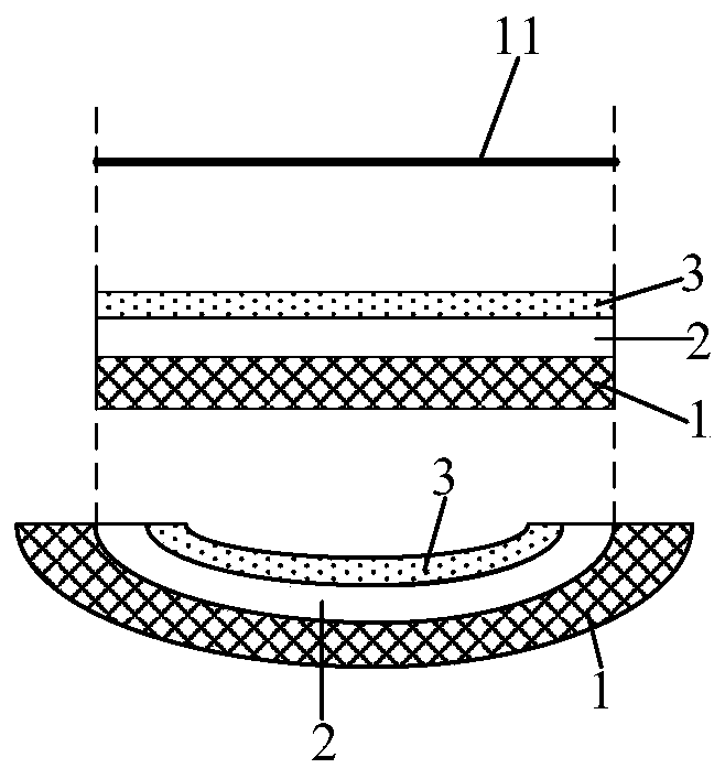
[0034] This embodiment provides an organic electroluminescent element, such as figure 2 As shown, it includes a first electrode 1, a light-emitting functional layer 2 and a second electrode 3, the light-emitting functional layer 2 is sandwiched between the first electrode 1 and the second electrode 3, and the light-emitting functional layer 2 is a curved plate structure.

[0035] Wherein, the light emitting functional layer 2 includes a hole transport layer, a hole injection layer, a light emitting layer, an electron transport layer, and an electron injection layer. Each film layer constituting the light-emitting functional layer 2 is a curved plate structure, and the curved plate structure of each film layer matches, thereby forming the light-emitting functional layer 2 with a curved plate structure. Alternatively, the luminescent functional layer 2 may only include a luminescent layer. The first electrode 1 is the anode of the organic electroluminescent element, and the se...

Embodiment 2

[0041] This embodiment provides an organic electroluminescent element, which is different from that in Embodiment 1, such as Figure 4 As shown, the luminescent functional layer 2 is an arc panel, and the arc panel is recessed toward the side where the second electrode 3 is located. Both the first electrode 1 and the second electrode 3 are arc panels matching the luminescent functional layer 2 .

[0042]The other structural configurations of the organic electroluminescent element in this embodiment and the principle of improving the lifetime are the same as those in Embodiment 1, and will not be repeated here.

Embodiment 3

[0044] This embodiment provides an organic electroluminescent element, which is different from Embodiment 1-2, such as Figure 5 As shown, the light-emitting functional layer 2 is a corrugated plate, and the wave peaks and troughs of the corrugated plate have the same shape and size. The first electrode 1 and the second electrode 3 are corrugated plates that match the light-emitting functional layer 2 .

[0045] It should be noted that the crests and troughs of the wave plate may also have the same shape but different sizes.

[0046] The other structural configurations of the organic electroluminescent element in this embodiment and the principle of improving the lifetime are the same as those in Embodiment 1, and will not be repeated here.

[0047] Beneficial effects of Embodiment 1-3: The organic electroluminescent element provided in Embodiment 1-3, by setting the light-emitting functional layer of the organic electroluminescent element as a curved plate structure, compared...


PUM


Abstract

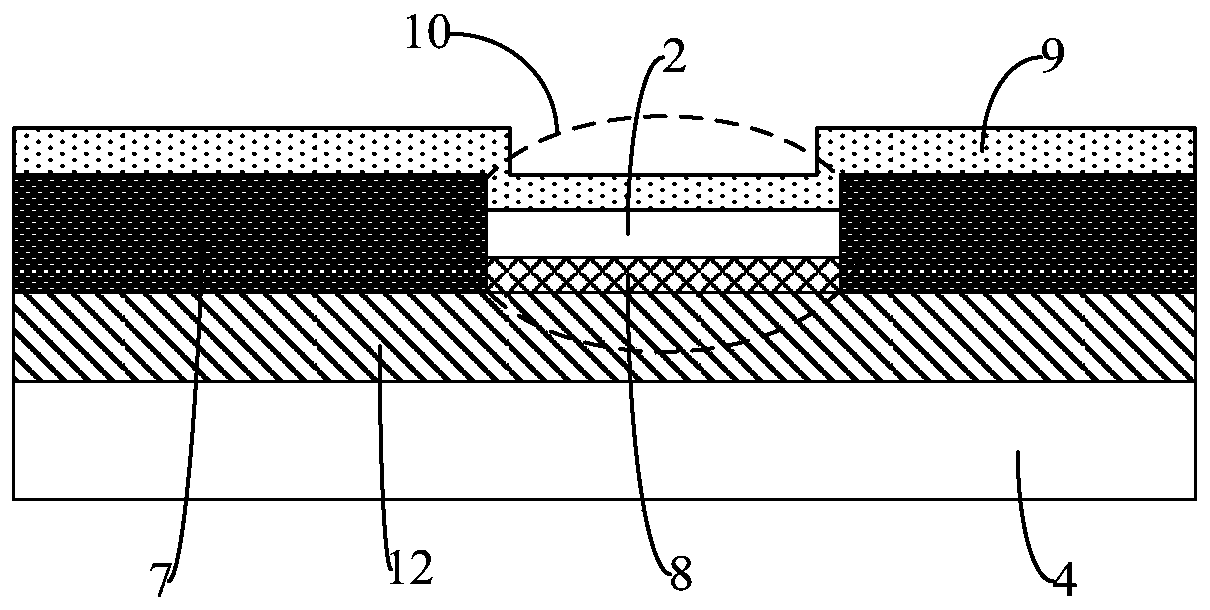
The invention provides an organic electroluminescence element, an array substrate and a preparation method thereof and a display panel. The organic electroluminescence element a first electrode, a luminescent function layer and a second electrode, and the luminescent function layer is clamped between the first and second electrodes and is of a curved plate structure. Compared with an organic electroluminescence element with a luminescent function layer of a planar plate structure with the same large light emitting area, the organic electroluminescence element of the invention can broaden the light emitting area of the organic electroluminescence element, and ensures that the voltage loaded by the organic electroluminescence element of the curved plate structure is obviously lower than thatloaded by the organic electroluminescence of the planar plate structure under the condition that the light emitting brightness of the organic electroluminescence element is not changed; and further heat radiation of the organic electroluminescence element is reduced, an exciton quenching phenomenon caused by higher temperature is solved to certain extent, exciton ageing is slowed, and the servicelife of the organic electroluminescence element is prolonged.

Description

technical field [0001] The present invention relates to the field of display technology, in particular to an organic electroluminescent element, an array substrate, a preparation method thereof, and a display panel. Background technique [0002] OLED (Organic Light-Emitting Diode, OLED) display panels are more and more used in smart display terminals due to their high contrast, wide color gamut, fast response, and bendability, becoming the next-generation display technology. [0003] OLED display panels usually include RGB (red, green, blue) three-color light-emitting elements. Under the condition of providing the same voltage, the heat radiation of the blue light-emitting elements is relatively high, and the excitons of the blue light-emitting elements burst when they are lit. The extinguishing phenomenon is more serious, resulting in a shorter lifespan of the blue light-emitting element, thereby resulting in a shorter lifespan of the OLED display panel. Contents of the i...

Claims


Application Information

Patent Timeline
Patent Type & Authority Applications(China)
IPC IPC(8): H01L51/50H01L51/56H01L27/32
Inventor 张娟王路焦志强
Owner BOE TECH GRP CO LTD
Why Eureka
Eureka Blog
Learn More