
Post-tensioned prestressing self centering steel plate shear wall structure

A steel plate shear wall and post-tensioning prestressing technology, which is applied to walls, building components, building structures, etc., can solve problems such as easy residual deformation, reduce cost and difficulty, and eliminate residual deformation.

Inactive Publication Date: 2014-06-18
SOUTHEAST UNIV
View PDF7 Cites 7 Cited by
  • Summary
  • Abstract
  • Description
  • Claims
  • Application Information

AI Technical Summary

Problems solved by technology

[0006] Technical problem: The present invention aims at the problem that the existing steel plate shear wall structure is prone to residual deformation under large earthquakes, and provides a method that can not only effectively eliminate the plastic deformation of the steel plate shear wall, realize the purpose of self-centering of the main body of the structure, but also can Ensure the coordination of the lateral deformation of the frame and the floor, thereby greatly reducing the repair cost and difficulty of the engineering structure after the earthquake, and at the same time, the post-tensioned prestressed self-centering steel plate shear wall structure can flexibly and independently control the strength, stiffness and ductility of the structure

Method used


Image

  • Post-tensioned prestressing self centering steel plate shear wall structure
  • Post-tensioned prestressing self centering steel plate shear wall structure
  • Post-tensioned prestressing self centering steel plate shear wall structure

Examples


Embodiment Construction

[0032] The technical solution of the present invention will be described in detail below in conjunction with the accompanying drawings.

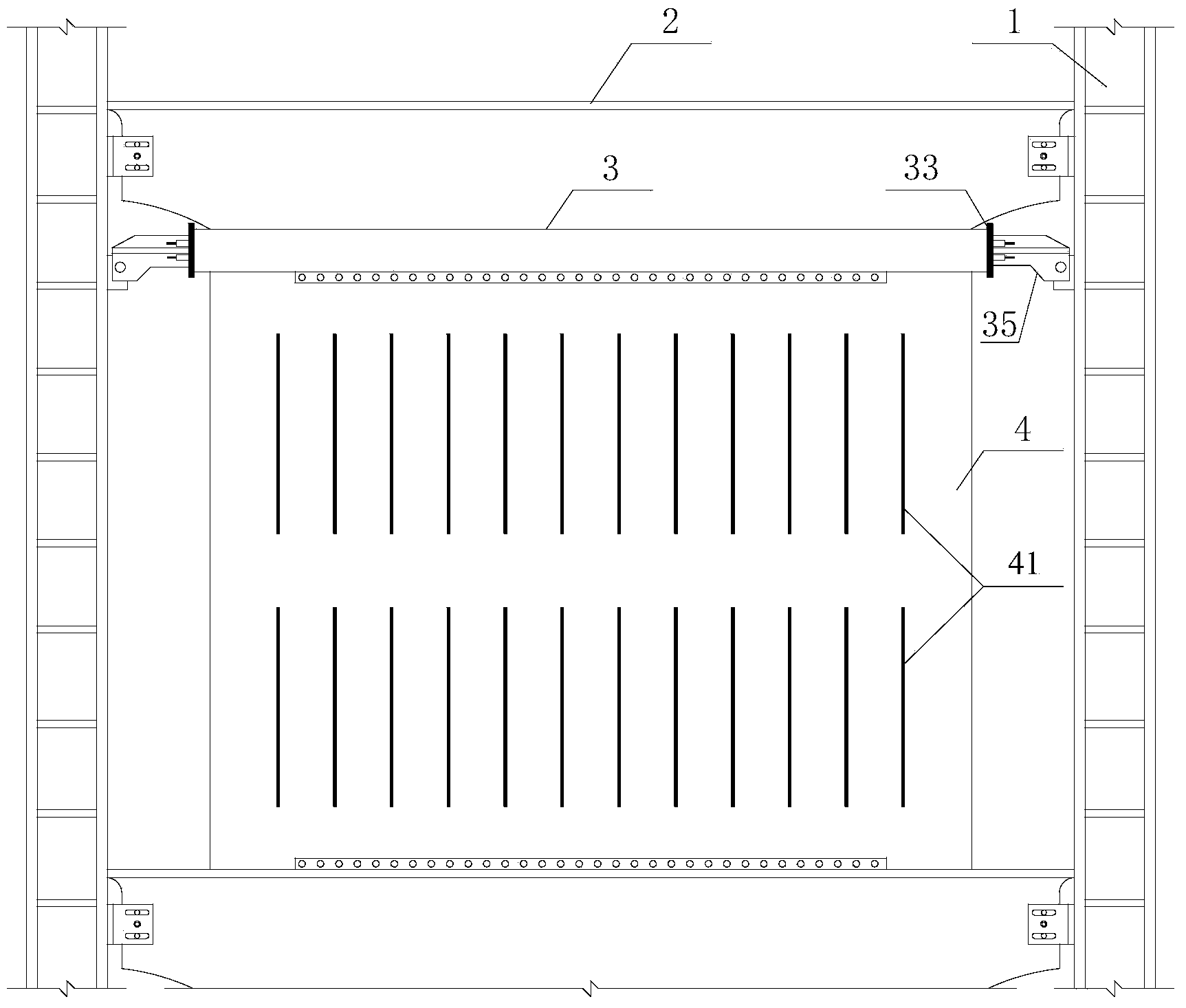
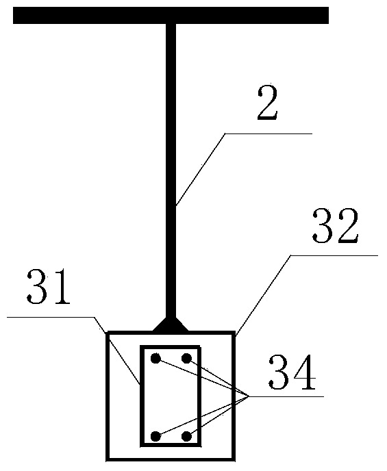
[0033] like figure 1 As shown, the post-tensioned prestressed self-centering steel plate shear wall structure of the present invention includes at least one structural unit, and each structural unit includes two steel frame columns 1, a T-shaped steel connecting the upper ends of the two steel frame columns 1 Beam 2, a self-centering connector 3 located on the lower side of the T-shaped steel beam 2 and connecting two steel frame columns 1, a steel plate shear wall 4 located under the self-centering connector 3, wherein the T-shaped steel beam 2 and the self-centering Both the centering connector 3 and the steel frame column 1 are hinged to avoid plastic hinges at the beam-column joints when the structure undergoes lateral deformation; the length of the upper flange of the T-shaped steel beam 2 is greater than the length of the web, Make th...


PUM


Abstract

The invention discloses a post-tensioned prestressing self centering steel plate shear wall structure, which comprises at least one structural unit, wherein the structural unit comprises two steel framework posts, a T-shaped steel beam, a self centering connecting element and a steel plate shear wall, wherein the T-shaped steel beam is connected with the upper ends of the two steel framework posts, the self centering connecting element is positioned at the lower side of the T-shaped steel beam and is connected with the two steel framework posts, the steel plate shear wall is positioned under the self centering connecting element, the self centering connecting element comprises an inner sleeve pipe, an outer sleeve pipe, an end plate, a pre-stretching rod and a connecting head, the inner sleeve pipe is sheathed by the outer sleeve pipe, the end plate seals the end parts of the inner sleeve pipe and the outer sleeve pipe, the pre-stretching rod is arranged in the inner sleeve pipe and is anchored on the end plate, the connecting head is connected with the end part of the inner sleeve pipe, the length of the upper wing edge of the T-shaped steel beam is greater than the length a the web plate, the lower end of the web plate of the T-shaped steel beam is connected with the upper side surface of the outer sleeve pipe, and the lower side surface of the outer sleeve pipe is connected with the upper side surface of the steel plate shear wall. The post-tensioned prestressing self centering steel plate shear wall structure has the advantages that the plastic deformation of the steel plate shear wall can be effectively eliminated, the lateral deformation coordination of a framework and a floor slab can be ensured, and the restoring cost and the restoring difficulty of the engineering structures after the earthquake are greatly reduced.

Description

technical field [0001] The invention belongs to the field of civil engineering and relates to a post-tensioned prestressed self-centering steel plate shear wall structure for reducing earthquake disasters of engineering structures. Background technique [0002] Earthquakes bring extremely serious disasters to human beings. The traditional seismic design adopts the ductility design method, that is, under the action of an earthquake, through the early yield and failure of some structural components, but the overall function will not be lost, relying on the plastic deformation of the components to dissipate most of the seismic energy, so as to achieve The purpose of ensuring the safety of the main structure. [0003] As a typical energy-dissipating and shock-absorbing technology, steel plate shear walls have been widely used in recent years due to their advantages such as strong energy-dissipating capacity, good shock-absorbing effect, and easy replacement after earthquakes. ...

Claims


Application Information

Patent Timeline
Patent Type & Authority Applications(China)
IPC IPC(8): E04B2/58E04B1/98
Inventor 周臻谢钦孟少平李德猛吴京王春林王维影
Owner SOUTHEAST UNIV
Learn More