
Welding supporting plate for printed circuit boards

A technology for printed circuit boards and pallets, applied in the field of electronic assembly, can solve problems such as clamping, and achieve the effects of improving production efficiency, convenient operation and simple structure

Inactive Publication Date: 2014-06-11
KUNSHAN PANTRATEQ
View PDF5 Cites 1 Cited by
  • Summary
  • Abstract
  • Description
  • Claims
  • Application Information

AI Technical Summary

Problems solved by technology

[0004] The object of the present invention is to provide a printed circuit board soldering plate, which has a simple structure, more convenient operation, solves the problem of clamping during use, and can also be used for printed circuit boards of different sizes, which can improve the processing quality and improve Yield rate, reduce the probability of repair and rework, improve production efficiency

Method used


Image

  • Welding supporting plate for printed circuit boards

Examples


Embodiment Construction

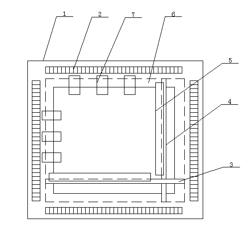
[0011] refer to figure 1 , the specific implementation adopts the following technical solutions: it includes a support frame 1, an adjustment scale 2, a lateral support beam 3, a longitudinal support beam 4, a fixed compression device 5, a track 6 and a movable compression device 7; Adjustment scales 2 are provided on the four sides, and several movable pressing devices 7 are provided on the inner side of the upper frame of the support frame 1 and the inner side of the left frame. The track 6 is movably connected with the support frame 1, and the horizontal support beam 3 and the longitudinal support beam 4 are both provided with fixed pressing devices 5.

[0012] The horizontal support beam 3 and the longitudinal support beam 4 can adjust the distance between them and the movable pressing device 7 through the track 6 according to the actual operation conditions, so as to meet the requirements of circuit boards of different specifications.

[0013] The fixing and pressing dev...


PUM


Abstract

The invention discloses a welding supporting plate for printed circuit boards and relates to the technical field of electronic assembly. The four sides of an outer supporting frame are provided with adjusting scales. A plurality of movable pressing devices are arranged on the inner side of the upper side and the inner side of the left side of the outer supporting frame. A transverse supporting beam and a longitudinal supporting beam are movably connected with the outer supporting frame through a rail on the inner side of the outer supporting frame and provided with fixed pressing devices. The welding supporting plate is simple in structure and convenient to operate, solves the clamping problem in the use process, and can be used for the printed circuit boards of different sizes, improve the processing quality, increase the rate of finished products, lower the probability of repair and rework and improve the production efficiency.

Description

Technical field: [0001] The invention relates to the technical field of electronic assembly, in particular to a printed circuit board welding support. Background technique: [0002] With the development of electronic assembly technology, there are more and more large-size printed circuit boards, and the possibility of deformation is greater. The reason is that during welding, the material in the molten state during preheating and welding will heat the printed circuit board, making the Lack of support. [0003] The existing pallet lacks compatibility, and needs to be separately completed in the process of design and manufacture, which increases the cost of design and manufacturing, and the structure of the currently used pallet is complex, difficult to process, and used during use The rivets are fixed, and the tightness of the rivets is difficult to grasp, which will affect the processing quality. Invention content: [0004] The object of the present invention is to p...

Claims


Application Information

Patent Timeline
Patent Type & Authority Applications(China)
IPC IPC(8): H05K3/34
Inventor 杨东明
Owner KUNSHAN PANTRATEQ
Learn More