
An antenna and antenna array system

An antenna and antenna unit technology, applied in antenna arrays, antennas, electrical components, etc., can solve the problems of difficult application of dipole antenna functions, narrow frequency band of dipole antennas, etc., to improve stable working ability, good antenna shape, maintain Effect of Antenna Shape

Active Publication Date: 2018-09-14
KUANG CHI INST OF ADVANCED TECH
View PDF6 Cites 0 Cited by
  • Summary
  • Abstract
  • Description
  • Claims
  • Application Information

AI Technical Summary

Problems solved by technology

[0003] Dipole antennas are also called symmetrical antennas and dipole antennas. Due to structural limitations, the frequency band covered by a general dipole antenna is relatively narrow, and the effective frequency band it covers cannot be well covered even after adjustment. Wide frequency band, so it is difficult to expand the frequency band covered by the dipole antenna and the effective frequency band to expand the functional application of the dipole antenna

Method used


Image

  • An antenna and antenna array system
  • An antenna and antenna array system
  • An antenna and antenna array system

Examples


Embodiment Construction

[0039] Reference will now be made in detail to the embodiments depicted in the accompanying drawings. In the following detailed description, numerous specific details are set forth in order to provide a thorough understanding of the present invention. However, it will be understood by those skilled in the art that the present invention may be practiced without these specific details. In other embodiments, well-known methods, procedures, components and circuits have not been described in detail so as not to unnecessarily obscure the embodiments.

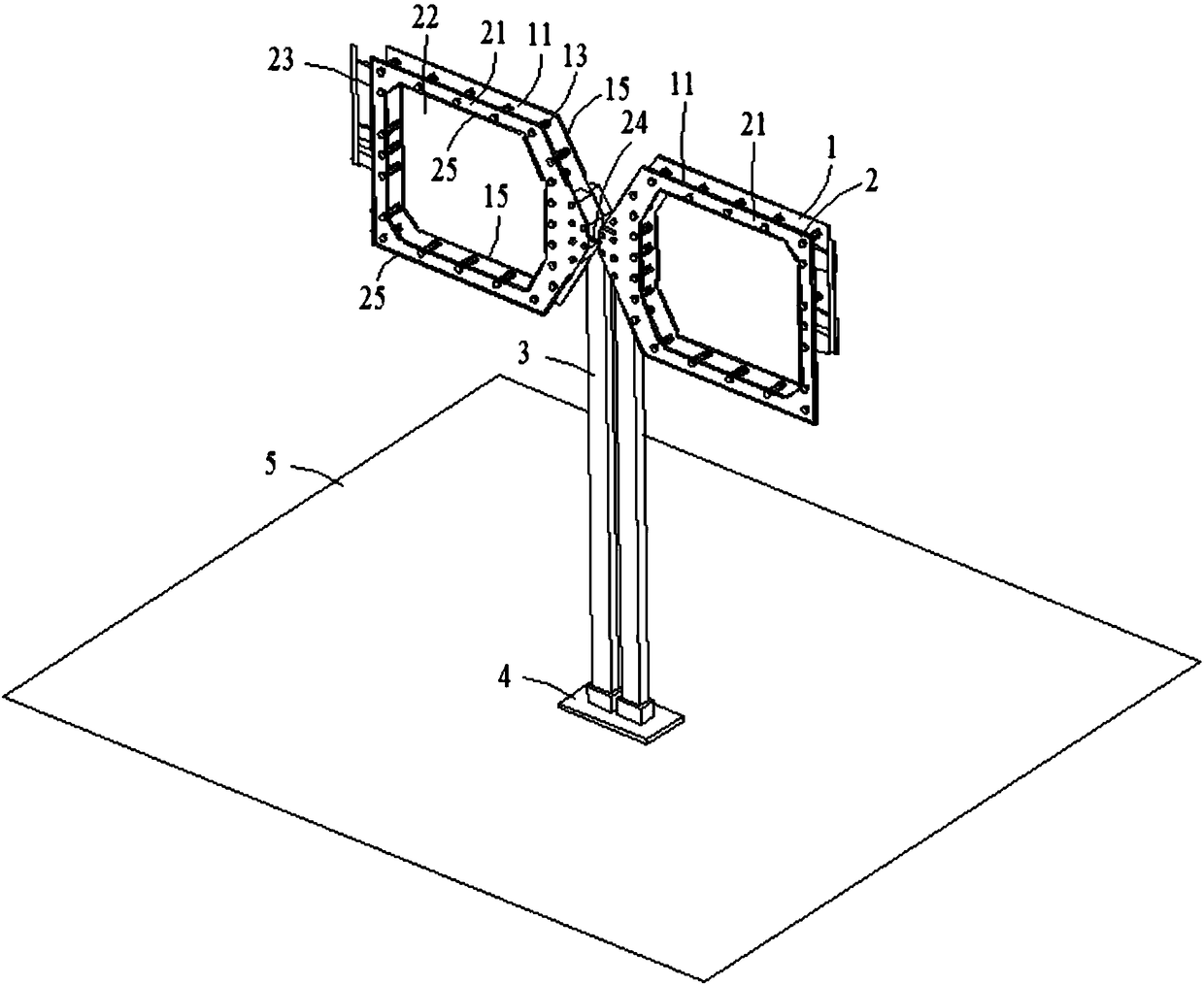
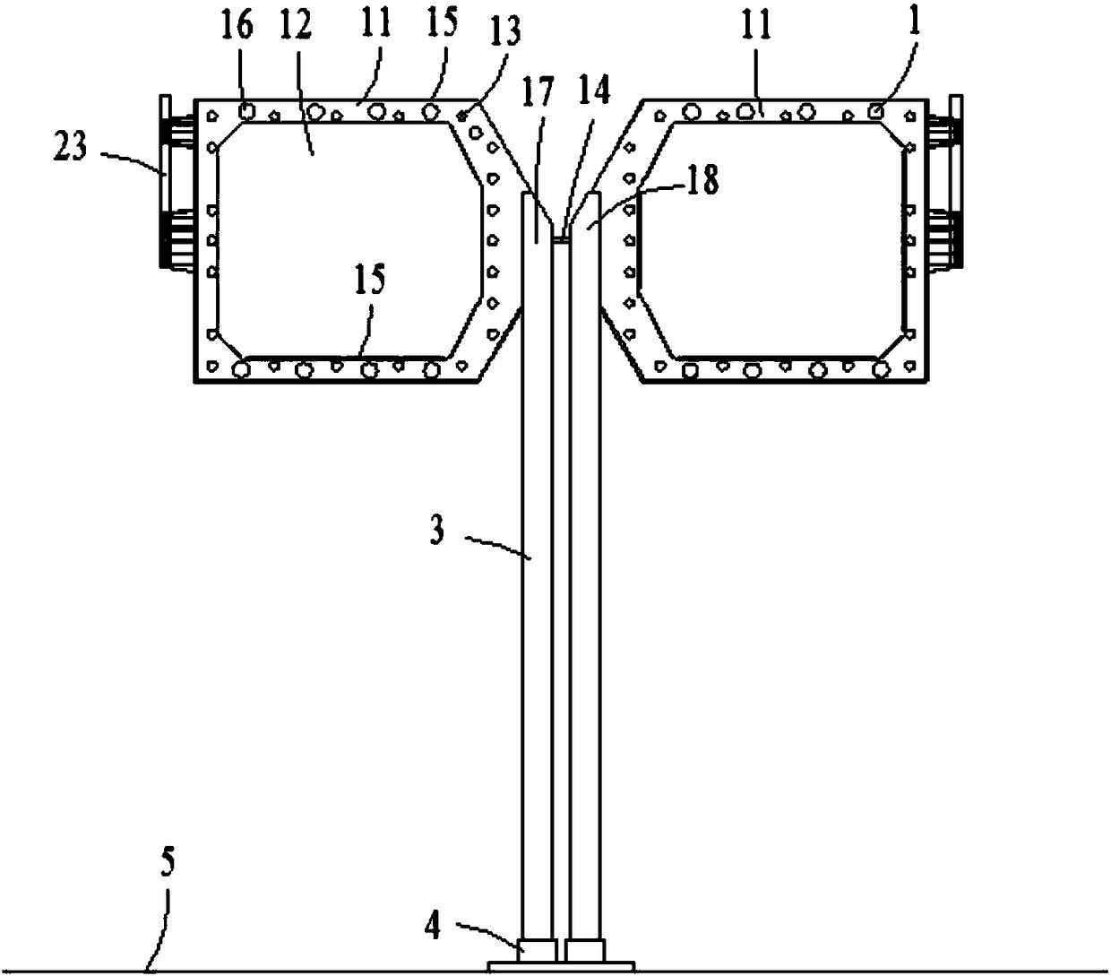
[0040] Such as figure 1 and figure 2 Shown is a structural schematic diagram of an embodiment of the antenna of the present invention, the antenna at least includes a first antenna unit 1 and a second antenna unit 2, a balun structure 3, a fixing seat 4 and a reflecting surface 5, the first antenna unit 1 and the The second antenna units 2 are arranged at intervals. In a specific implementation process, the reflective surface 5 m...


PUM


Abstract

The embodiment of the invention discloses an antenna and an antenna array system. The antenna comprises a first antenna unit and a second antenna unit, wherein the first antenna unit is provided with a feed part and two first dipole subunits, and the two first dipole subunits are connected in a reactive mode; the second antenna unit comprises two second dipole subunits which are in reactive connection; the first antenna unit and the second antenna unit are arranged in a spaced mode, and the first antenna unit enables the second antenna unit to generate electromagnetic resonance in a coupled mode. A response frequency band is expanded in a double-vibrator mode, the electromagnetic signal response bandwidth of the antenna is increased, and the demand of wireless communication is met; meanwhile, the antenna has the advantages of being high in mechanical strength and capable of being little influenced by the external environment, the antenna form can be excellently maintained, and steady operation capacity of the antenna is improved.

Description

【Technical field】 [0001] The invention relates to the field of electromagnetic wave devices, and more specifically, to an antenna and an antenna array system. 【Background technique】 [0002] With the rapid development of wireless technology, the requirements for antennas, which play an extremely important role in wireless technology, are also getting higher and higher. In some environments, the antenna needs a wider communication frequency band, that is, a broadband antenna. The so-called broadband antenna refers to an antenna whose directivity, impedance and polarization characteristics remain almost unchanged in a wide band. At present, some broadband Antennas mainly include rhombus antennas, V-shaped antennas, double wave antennas, disc-conical antennas, etc., as well as the latest development of log-periodic antennas. [0003] Dipole antennas are also called symmetrical antennas and dipole antennas. Due to structural limitations, the frequency band covered by a general ...

Claims


Application Information

Patent Timeline
Patent Type & Authority Patents(China)
IPC IPC(8): H01Q1/36H01Q21/00
Inventor 刘若鹏徐冠雄尹柳中
Owner KUANG CHI INST OF ADVANCED TECH
Learn More