The adjustment structure of the illumination direction and angle of the lamp

A technology for adjusting the structure and orientation, applied in the parts of lighting devices, lighting devices, lighting auxiliary devices, etc., can solve the problems of reducing work efficiency, unfavorable safe operation of equipment, danger of lamps and lanterns, etc., to improve the safety of use, design and processing The effect of low cost and avoiding climbing work

Active Publication Date: 2016-02-03
OCEANKING DONGGUAN LIGHTING TECH +2
View PDF13 Cites 0 Cited by
  • Summary
  • Abstract
  • Description
  • Claims
  • Application Information

AI Technical Summary

Problems solved by technology

[0004] However, in actual situations, the following two situations are often encountered: one is when there is no tool and the position and angle of the lamp cannot be directly adjusted manually, and the other is when the installation position of the lamp is relatively high. It is not easy to adjust the position and angle of the lamp irradiation. On the one hand, it will take a lot of time to find tools or try to climb to the same height as the lamp, which will greatly reduce the work efficiency; The phenomenon that the adjustable tool cannot be found due to limited conditions or cannot climb to the same height as the lamp, so that it is impossible to adjust the irradiation direction and angle of the lamp, thus greatly reducing the irradiation effect of the lamp; at the same time, the height adjustment There are certain dangers in the direction and angle of the lighting, which is not conducive to the safe operation of the equipment.

Method used


Image

  • The adjustment structure of the illumination direction and angle of the lamp
  • The adjustment structure of the illumination direction and angle of the lamp
  • The adjustment structure of the illumination direction and angle of the lamp

Examples


Embodiment Construction

[0024] In order to make the object, technical solution and advantages of the present invention clearer, the present invention will be further described in detail below in conjunction with the accompanying drawings and embodiments. It should be understood that the specific embodiments described here are only used to explain the present invention, not to limit the present invention.

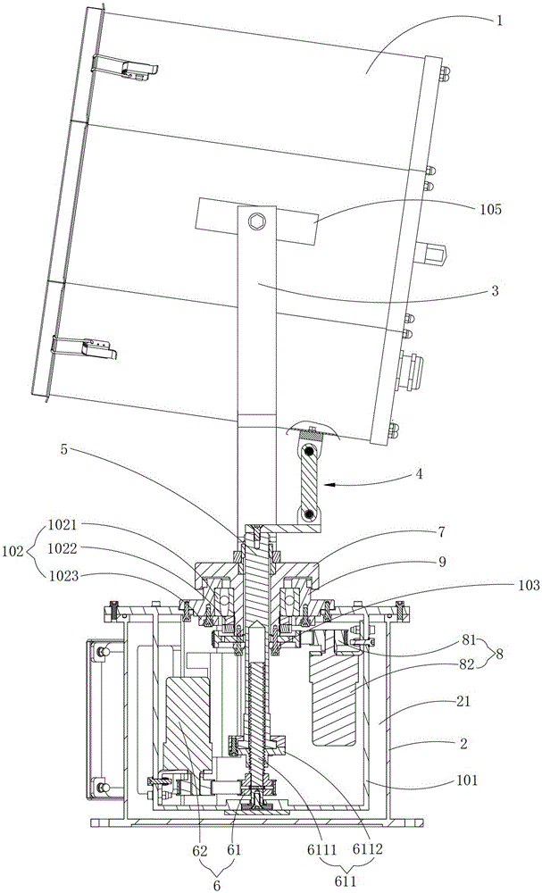
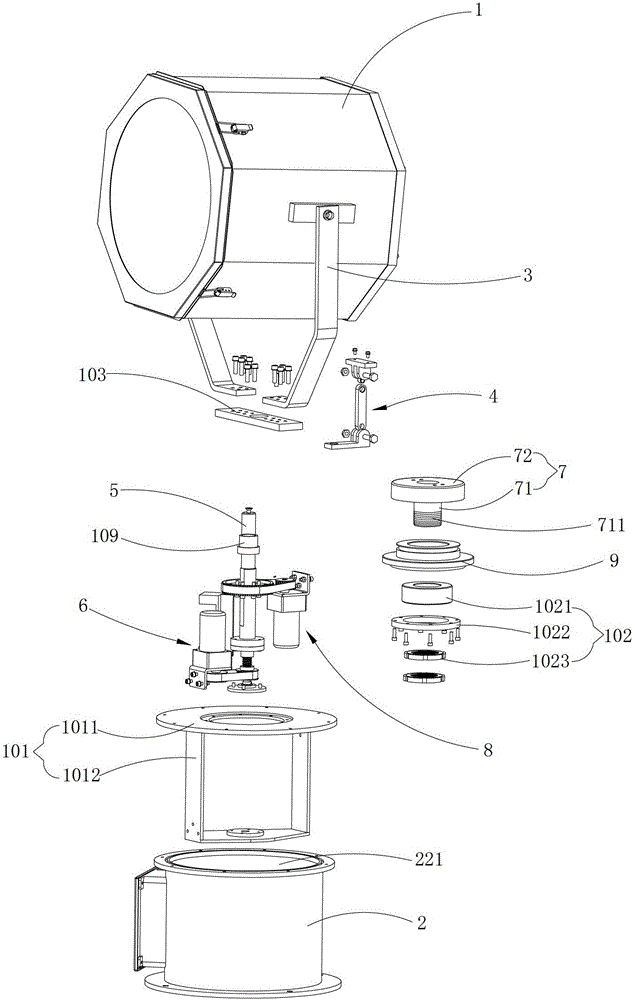
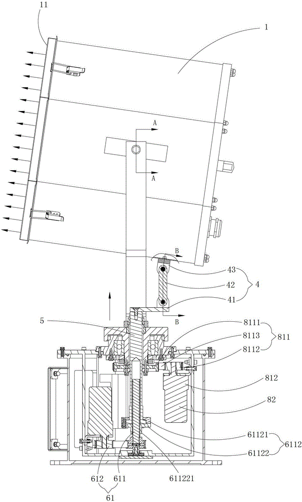
[0025] Such as figure 1 with figure 2 As shown, the adjusting structure of the lighting direction and angle of the lamp provided by the embodiment of the present invention includes a lamp body 1, a fixing seat 2 having an inner cavity 21, and a bracket 3 for fixing the lamp body 1 on the fixing seat 2, for The connecting rod assembly 4 driving the lamp body 1 to swing, the push rod 5 used to drive the connecting rod assembly 4 to move, the first power mechanism 6 used to drive the push rod 5 to move up and down, the turntable 7 used to drive the lamp body 1 to rotate, The second power mechanism ...


PUM


Abstract

The invention is applicable to the technical field of lamp mounting and discloses an adjusting structure of lamp irradiating directions and angles. The adjusting structure comprises a lamp body, a fixing seat with an inner cavity, a support, a connecting rod component for driving the lamp body to swing, a push rod for driving the connecting rod component to move, a first power mechanism for driving the push rod to move up and down, a rotary disc for driving the lamp body to rotate, and a second power mechanism for driving the rotary disc to rotate. The first power mechanism and the second power mechanism are disposed in the inner cavity of the fixing seat. The rotary disc is inserted into the fixing seat in a clamped manner. The bottom end of the rotary disc extends into the inner cavity to be connected with the second power mechanism. One end of the support is connected with the rotary disc, and the other end thereof is connected with the lamp body. The bottom end of the push rod is connected with the first power mechanism. The top end of the push rod penetrates the rotary disc to be connected with one end of the connecting rod component. The other end of the connecting rod component is connected with the lamp body. The adjusting structure has the advantages that lamp irradiating directions and angles can be remotely controlled by controlling the operation of the first power mechanism and the second power mechanism, and the adjusting structure is simple to operate and high in adjusting precision.

Description

technical field [0001] The invention belongs to the technical field of lamp installation, and in particular relates to a structure for adjusting the irradiation direction and angle of a lamp. Background technique [0002] In the prior art, the installation structure of a lamp generally includes a lamp body, a bracket and a fixing seat. One end of the bracket is connected to the lamp body, and the other end is connected to the fixing seat. In this way, the lamp body is effectively fixed on the fixing seat through the bracket. [0003] In specific applications, in order to make the illumination effect of the lamp better, the orientation and angle of the illumination of the lamp are often adjusted according to specific needs. In the prior art, when it is necessary to adjust the illumination angle of the lamp, it is generally necessary to use a tool (screwdriver or wrench) or directly loosen the connection between the lamp body and the bracket by hand, and then change the lamp b...

Claims


Application Information

Patent Timeline
Patent Type & Authority Patents(China)
IPC IPC(8): F21V21/14
Inventor 周明杰彭冬来
Owner OCEANKING DONGGUAN LIGHTING TECH
Why Eureka
Try Eureka