
Gas turbine temperature measurement

A technology of gas turbine and gas, applied in the direction of gas turbine engine testing, temperature measurement of moving fluid, gas turbine device, etc.

Inactive Publication Date: 2014-06-11
ANSALDO ENERGIA SWITZERLAND AG
View PDF8 Cites 10 Cited by
  • Summary
  • Abstract
  • Description
  • Claims
  • Application Information

AI Technical Summary

Problems solved by technology

However, engine noise has so far prevented the use of this concept

Method used


Image

  • Gas turbine temperature measurement
  • Gas turbine temperature measurement
  • Gas turbine temperature measurement

Examples


Embodiment Construction

[0109] The same or functionally equivalent elements are provided with the same reference numbers below. The examples do not limit the invention to such an arrangement in any way.

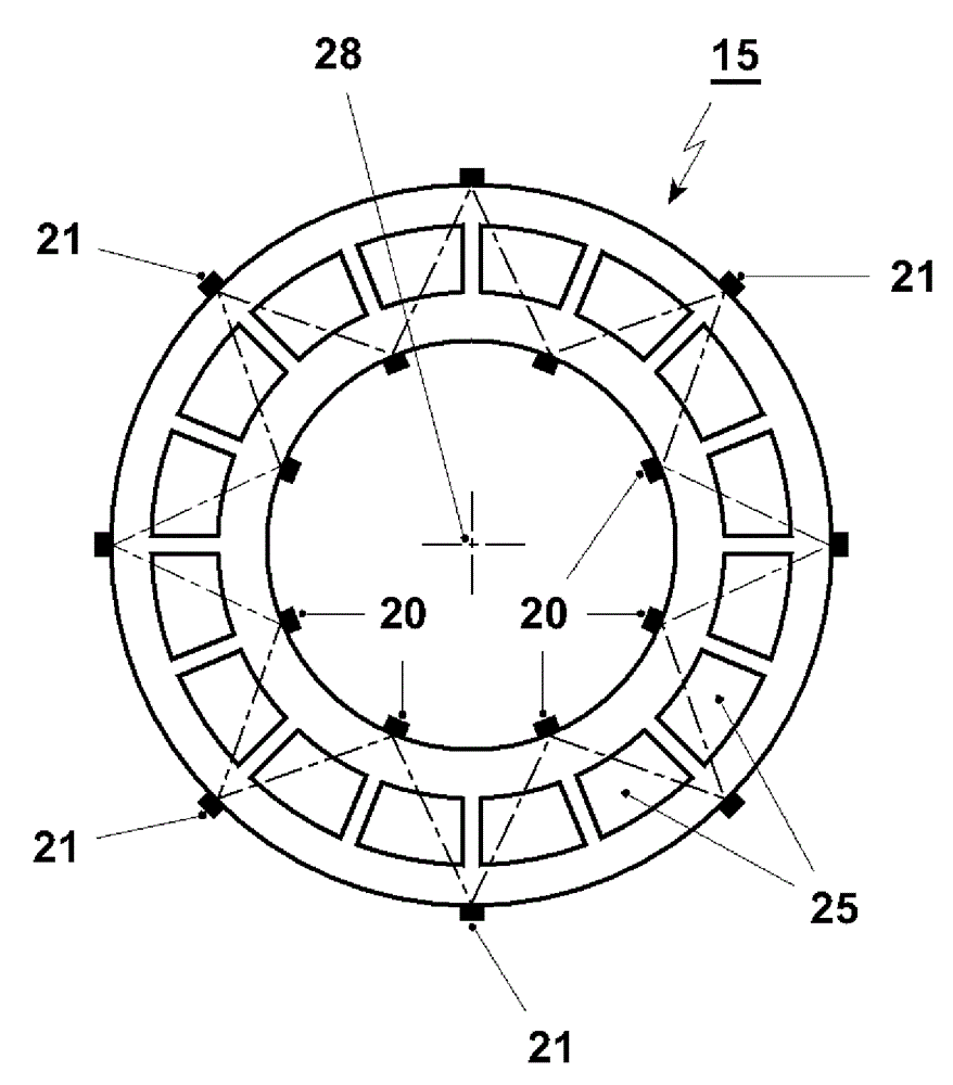
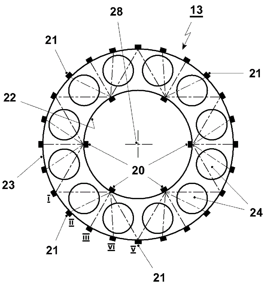
[0110] in figure 1 An exemplary arrangement is shown schematically in. The gas turbine 10 is provided with a compressor inlet gas 11. In the gas turbine 10, the compressor 12 is followed by a first combustor, and the first combustor includes a first burner 24 and a first combustion chamber 13. In the first burner 34, the fuel 37 is added to the compressed gas, and the mixture is burned in the first combustion chamber 13. The hot combustion gases are fed from the first combustion chamber 13 to the first turbine 14. After the first turbine 14 is a second combustor. The second combustor includes a sequential burner 25 (also called a second burner) And the sequential combustion chamber 15 (also called the second combustion chamber). The fuel 37 may be added to the gas leaving the first turbine 14 in t...


PUM


Abstract

Method for determining a temperature in a pressurized flow path of a gas turbine (10) comprising the steps of sending an acoustic signal from an acoustic signal emitting transducer (20, 21) across a section of the pressurized flow path, detecting the acoustic signal with a receiving transducer (20, 21), measuring the time needed by the acoustic signal to travel from the acoustic signal emitting transducer (20, 21) to the receiving transducer (20, 21), calculating the speed of sound, and calculating the temperature as a function of the speed of sound, the heat capacity ratio (kappa) and a specific gas constant (R spec ) of the gas flowing in the pressurized flow path. Gas turbine with a processor and transducers arranged to carry out such a method is disclosed.

Description

Technical field [0001] The present invention relates to measuring the temperature in the pressurized flow path of a gas turbine, and the use of such measurement when controlling the gas turbine, and a gas turbine including such measurement. Background technique [0002] It is known to measure the different temperatures of the gas turbine. Typically, these measurements are based on thermocouples or resistance thermometers. However, due to the harsh environment in the gas turbine, the thermocouple or resistance thermometer needs to be enclosed for use in the pressurized flow path, and therefore the instantaneous change of the detected temperature is relatively slow. In addition, the temperature of the hot gas in a gas turbine is often too high to use direct measurement. [0003] An optical pyrometer was also used as a way to obtain field readings (mainly in the combustion zone). Optical pyrometers are not widely used as continuous measurement devices in gas turbines. They cannot ...

Claims


Application Information

Patent Timeline
IPC IPC(8): F02C9/00G01K11/24
CPCG01K13/02F02C9/28F05D2270/303G01K11/24G01K2013/024G01N33/225G01M15/14F05D2270/80F02C6/003G01K13/024Y02E20/14
Inventor W.朗J.霍夫曼恩
Owner ANSALDO ENERGIA SWITZERLAND AG
Learn More