Blast-furnace casting runner

A technology for blast furnace tapping and blast furnace molten iron, which is applied in the direction of discharge device, etc., can solve the problems of skimmer burning and leakage, damage to the shape of the hole, affecting normal iron passing, etc., and achieves the effect of convenient dismantling and installation.

Active Publication Date: 2014-06-11
CENT RES INST OF BUILDING & CONSTR CO LTD MCC GRP +2
View PDF2 Cites 5 Cited by
  • Summary
  • Abstract
  • Description
  • Claims
  • Application Information

AI Technical Summary

Problems solved by technology

The problems that are prone to occur in the skimmer 20 include: ①The skimmer cracks; ②The molten iron condenses, which makes the iron passage channel smaller and affects the normal iron passing; ③The skimmer burns and leaks, etc.
Due to the high strength of the castable filling the residual iron channel 40, when the residual iron channel 40 is opened by mechanical drilling, the drill bit will be great

Method used


Image

  • Blast-furnace casting runner
  • Blast-furnace casting runner
  • Blast-furnace casting runner

Examples


Example Embodiment

[0022] The embodiments of the blast furnace tapping channel according to the present invention will be described below with reference to the drawings. Those of ordinary skill in the art can realize that the described embodiments can be modified in various ways without departing from the spirit and scope of the present invention. Therefore, the drawings and description are illustrative in nature, and are not used to limit the protection scope of the claims. In addition, in this specification, the same reference numerals indicate the same or similar parts.

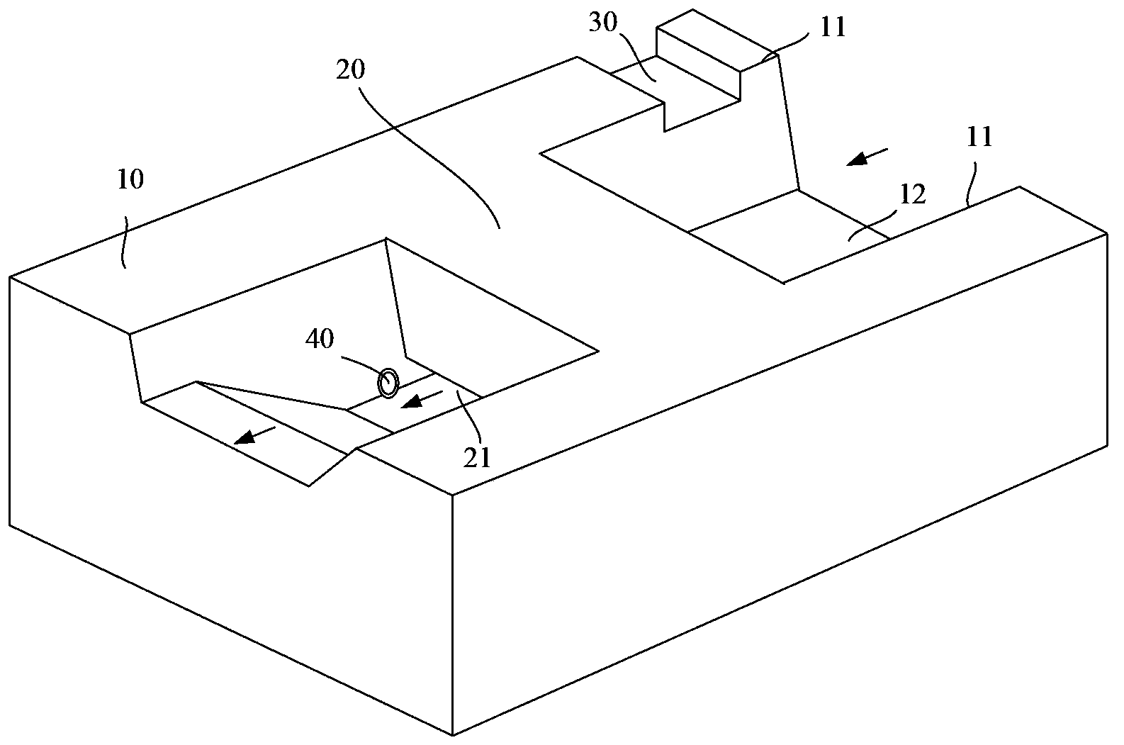
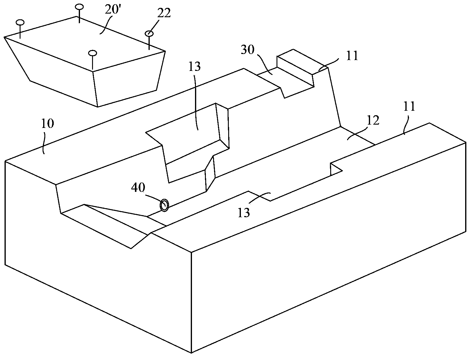
[0023] figure 2 It is a perspective view showing the structure of a section of the blast furnace iron trough before installing the prefabricated skimmer according to an embodiment of the present invention, image 3 It is a perspective view showing the structure of a section of the blast furnace tapping channel after the prefabricated skimmer is installed according to an embodiment of the present invention, Figure 4a Is a cros...


PUM


Abstract

A provided blast-furnace casting runner comprises a runner body for enabling blast furnace melted iron to flow past, prefabricated slag skimmers detachably embedded in two runner edges of the runner, a slag removing channel communicated with the runner body, and an residual iron discharging taphole communicated with the runner body; an iron passing channel is formed between the bottom surfaces of the prefabricated slag skimmers and the bottom surface of the runner body; the communication opening between the slag removing channel and the runner body is at the runner edge which blast furnace molten iron flows past preceding to the prefabricated slag skimmers; and the communication opening between the residual iron discharging taphole and the runner body is at the lowest position of the bottom of the runner body. The provided blast-furnace casting runner possesses the detachable slag skimmers, and the slag skimmer is not easy to crack and convenient for changing; and additionally, the provided blast-furnace casting runner possesses the improved residual iron discharging taphole, and the improved residual iron discharging taphole helps to avoid taphole enlargement or taphole shape destroying when the residual iron discharging taphole is gotten through.

Description

technical field [0001] The invention relates to the field of ironmaking auxiliary equipment, in particular to a blast furnace tapping trough. Background technique [0002] After the iron ore is smelted in the blast furnace, it becomes molten iron and slag flows out from the tap hole of the blast furnace, enters the tap trough, and flows away along the tap trough. [0003] figure 1 It is a three-dimensional schematic diagram of an existing blast furnace tapping trough. like figure 1 As shown, this section of the blast furnace tapping trough includes a ditch body 10 , a skimmer 20 , a slag removal channel 30 and a residual iron discharge channel 40 . The ditch body 10 includes two ditch edges 11 and a ditch bottom 12, along which the blast furnace molten iron figure 1 Flow in the groove body 10 in the direction indicated by the arrow in . The skimmer 20 spans between two ditch edges 11 of the ditch body 10 , and an iron passage 21 is formed between the bottom surface of t...

Claims


Application Information

Patent Timeline
IPC IPC(8): C21B7/14
Inventor 徐自伟潘有斌徐焱慧刘兴平唐勋海范咏莲
Owner CENT RES INST OF BUILDING & CONSTR CO LTD MCC GRP
Why Eureka
Try Eureka