
Graduated guide pin for use in medical treatment

A medical and scaled technology, applied in the direction of application, guide wire, medical science, etc., can solve problems such as fracture joints and injuries

Inactive Publication Date: 2014-06-11
TAMA MEDICAL
View PDF5 Cites 1 Cited by
  • Summary
  • Abstract
  • Description
  • Claims
  • Application Information

AI Technical Summary

Problems solved by technology

[0003] The bone is composed of cortical bone (cortical bone) consisting of a hard part on the outside and cancellous bone (cancellous bone) consisting of a mesh part on the inside. When joining, it will penetrate the bone too much and damage the subcutaneous tissues on the opposite side. Conversely, if the screw is too short, it will stop in the cancellous bone and cannot be smoothly fixed because the screw is not sufficiently fixed. Join the fracture site

Method used


Image

  • Graduated guide pin for use in medical treatment
  • Graduated guide pin for use in medical treatment
  • Graduated guide pin for use in medical treatment

Examples


Embodiment 1

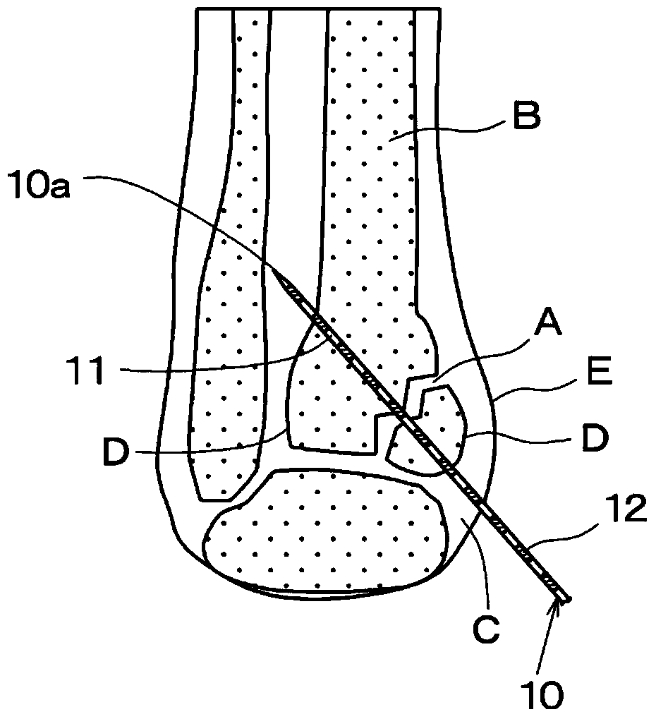
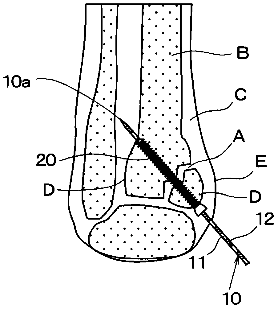
[0029] figure 1 It is a side view of the graduated medical guide pin (hereinafter simply referred to as guide pin) 10 of the first embodiment. The guide pin 10 has a diameter of 2 mm to 4 mm and a total length of about 30 cm. A tapered edge is provided at the front end portion 10a of the guide pin 10, and the tapered edge is sharp. The base material 11 of the guide pin 10 is divided into predetermined intervals along the longitudinal direction, for example, at intervals of 5 mm. The base material 11 is made of a radiation-transmitting metal or the like. Every other scale divided at intervals of 5 mm, the peripheral surface fixing material 12 is mounted on the base material 11 by gold plating, painting, welding and pasting. The peripheral surface fixing member 12 is made of a radiopaque metal. The surface of the graduated medical guide pin 10 on which the peripheral surface fixing material 12 is attached to the base material 11 is flat.

[0030] The guide pin 10 can be in...

Embodiment 2

[0040] If the guide pin 10 of Example 1 is used repeatedly, the peripheral surface fixing material 12 may peel off from the base material 11 by friction. Thus, in Figure 5 In the guide pin 10' of the illustrated embodiment 2, annular recesses 11" are provided at intervals of predetermined intervals of the base material 11' made of a radiation-transmissive metal. The formed peripheral fixing material 12' is disposed in the annular recess 11" by pasting, embedding, implanting, etc., and the surface is flat.

[0041] In this guide pin 10, peeling of the peripheral surface fixing member 12 does not occur. In addition, even if the base material 11' is only provided with the concave portion 11", the length can be measured by counting the unevenness in the X-ray image. However, since the surface of the guide pin 10' is uneven, it cannot be smoothly inserted into the subcutaneous tissue C, and cause damage. Or in the case of piercing into the fracture site A, sometimes the strength...


PUM

PropertyMeasurementUnit
thicknessaaaaaaaaaa

Abstract

The present invention discloses graduated guide pin for selecting an optimal length of a screw for connecting a fractured bone. The guide pin (10) is a base material (11) which is divided at specific interval and made of radiotransparent metal. Circumferential fixation materials (12) made of radioopaque metal are mounted in the zones of every two dividing. The base material (11) is made of titanium or titanium alloy which are easy to be transmitted by radioactive rays, and the circumferential fixation material is made of platinum, iridium, tungsten, tantalum, and gold or the alloys thereof which are hard to be transmitted by radioactive rays. In X-ray images which are shot by transmission X-ray or X-ray, the guide pin (10) reflects the dark parts which are formed by the circumferential fixation materials (12) and the light part which are formed by the base material (11) at specific intervals in an alternating manner, so that the thickness of the bone (B) including the fractured bone is obtained, through counting the scales formed by the dark parts and the light parts in the bone (B).

Description

technical field [0001] The present invention relates to a graduated medical guide pin which is inserted into a bone as a length measuring device when jointing a fracture site. Background technique [0002] Conventionally, when a fracture occurs due to an accident or exercise, for example, a medical screw called a cannulated screw has been used to join the fracture site separated by the fracture. In this splicing work, the fracture site is fixed with screws of appropriate length. [0003] The bone is composed of cortical bone (cortical bone) consisting of a hard part on the outside and cancellous bone (cancellous bone) consisting of a mesh part on the inside. When joining, it will penetrate the bone too much and damage the subcutaneous tissues on the opposite side. Conversely, if the screw is too short, it will stop in the cancellous bone and cannot be smoothly fixed because the screw is not sufficiently fixed. Join the fracture site. [0004] The joint operation of the fr...

Claims


Application Information

Patent Timeline
Patent Type & Authority Applications(China)
IPC IPC(8): A61B17/58A61B5/107
CPCA61B17/846A61B17/164A61B2019/462A61M2025/09166A61B2019/5466A61B17/848A61B17/86A61B2090/062A61B2090/3966A61B17/56A61B5/107
Inventor 町田英一
Owner TAMA MEDICAL
Learn More