Battery cell, manufacturing method thereof, and battery module including the same
A battery cell and battery module technology, applied to large-size batteries/battery packs, small-size batteries/battery packs, batteries, etc., can solve the problems of disconnection of power supply and lower productivity, achieve miniaturization and improve manufacturing The effect of high efficiency and easy power connection
- Summary
- Abstract
- Description
- Claims
- Application Information
AI Technical Summary
Problems solved by technology
Method used
Image
Examples
no. 1 example
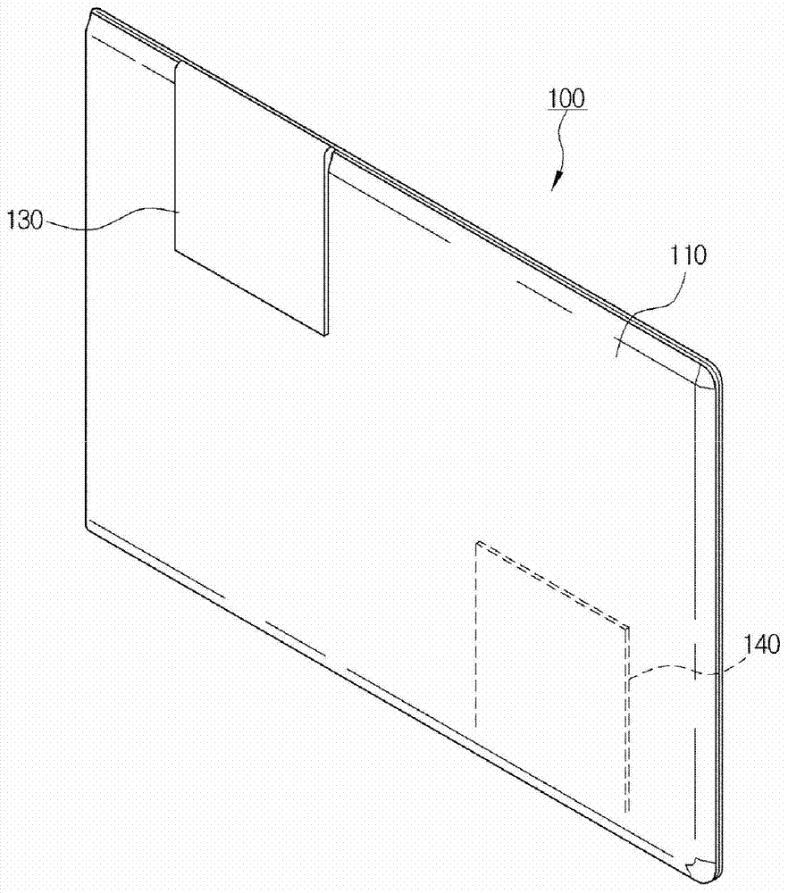
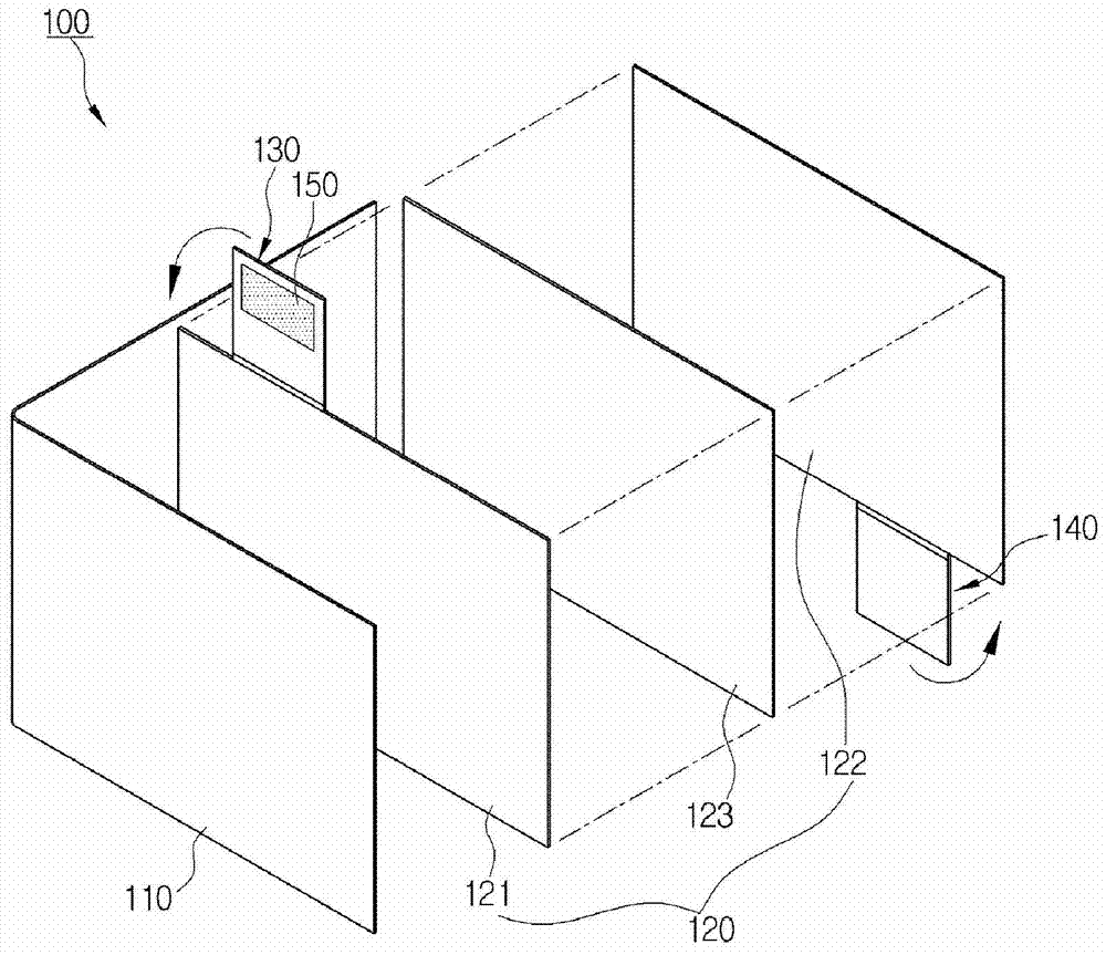
[0070] figure 1 and figure 2 It is a perspective view and an exploded perspective view showing the battery unit 100 of the first embodiment of the present invention.
[0071] At this time, an example is shown in which the first electrode sheet 130 and the second electrode sheet 140 are bent and fixed to the outer surface of the casing 110 by the adhesive 150 .
[0072] That is, the adhesive 150 is coated on one side of the first electrode sheet 130, and the part of the first electrode sheet 130 coated with the adhesive 150 is bonded to the outer surface of one side of the casing 110, whereby the first electrode sheet The other side of 130 is located on one side of the housing 110 .
[0073] And, the adhesive 150 is coated on one side of the second electrode sheet 140, and the part of the second electrode sheet 140 coated with the adhesive 150 is bonded to the outer surface of the other side of the casing 110, whereby the second electrode The other side of the sheet 140 is ...
no. 2 example
[0076] image 3 It is an exploded perspective view showing the battery cell 100 of the second embodiment of the present invention, showing the same structural features as the first embodiment described above, but the first electrode sheet 130 and the second electrode sheet 140 are oriented in the same direction (accompanying drawing An example in which the upper side direction in ) protrudes and is formed, and the pouch-shaped housing 110 is bent and joined at the lower side.
[0077] The first embodiment and the second embodiment described above are some embodiments of the present invention, and the present invention is not limited thereto, and can be formed in various ways by adjusting the formation positions of the first electrode sheet 130 and the second electrode sheet 140 .
no. 3 example
[0079] Figure 4 and Figure 5 It is a perspective view and an exploded perspective view showing a battery unit 100 according to a third embodiment of the present invention.
[0080] Figure 4 and Figure 5 The battery unit 100 shown in the third embodiment of the present invention shows that the first electrode sheet 130 and the second electrode sheet 140 are fixed on the inner surface of the casing 110, and a first hollow portion 111 and a second hollow portion 112 are formed in the casing 110 , an example in which certain areas of the first electrode sheet 130 and the second electrode sheet 140 are exposed to the outside of the case 110 .
[0081] In more detail, the first electrode sheet 130 and the second electrode sheet 140 can be fixed on the inner surface of the casing 110 through the adhesive 150, and the adhesive 150 is arranged on the periphery of the first electrode sheet 130 and the second electrode sheet 140 part, forming a certain space inside.
[0082] At ...
PUM
 Abstract
Description
Claims
Application Information
 - Generate Ideas
- Intellectual Property
- Life Sciences
- Materials
- Tech Scout
- Unparalleled Data Quality
- Higher Quality Content
- 60% Fewer Hallucinations
Browse by: Latest US Patents, China's latest patents, Technical Efficacy Thesaurus, Application Domain, Technology Topic, Popular Technical Reports.
© 2025 PatSnap. All rights reserved.Legal|Privacy policy|Modern Slavery Act Transparency Statement|Sitemap|About US| Contact US: help@patsnap.com


